Infiniti F50. Manual - part 551


  Index      Infiniti     Infiniti F50 - service repair manual 2006 year


Search            


Content   ..  549  550  551  552   ..


Infiniti F50. Manual - part 551


CYLINDER BLOCK

EM-91

C

D

E

F

G

H

I

J

K

L

M

A

EM

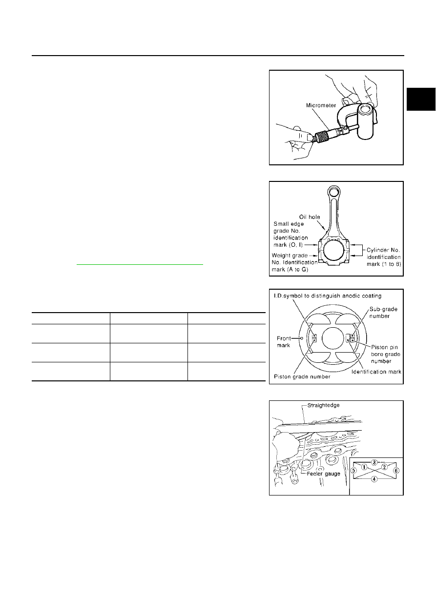
Outer Diameter of Piston Pin

Measure outer diameter of piston pin.

Connecting Rod Bushing Oil Clearance (Small End)

(Connecting rod small end oil clearance) = (Inner diameter of con-
necting rod small end) – (Outer diameter of piston pin)

If the measured value exceeds the standard, replace the con-
necting rod assembly and/or piston and piston pin assembly.

If replacing the piston and piston pin assembly, refer to the Table
for Selective Fitting for Piston to select the piston corresponding
to the applicable bore grade of the cylinder block to be used.
Refer to 

EM-82, "HOW TO SELECT PISTON"

 .

Factory installed parts grading:
Service parts apply only to grade 0.

Unit: mm (in)

CYLINDER BLOCK DISTORTION

Using a scraper, remove gasket on the cylinder block surface,
and also remove engine oil, scale, carbon, or other contamina-
tion. 

CAUTION:

Be careful not to allow gasket flakes to enter the engine oil
or engine coolant passages.

Measure the distortion on the block upper face at some different
points in 6 directions.

If out of the distortion limit, replace the cylinder block.

Standard

: 21.989 - 22.001 mm (0.8657 - 0.8662 in)

PBIC0117E

Standard

: 0.005 - 0.017 mm (0.0002 - 0.007 in)

PBIC0103E

Grade

0

1

Connecting rod small end 
inner diameter

         22.000 - 22.006          

(0.8661 - 0.8664)

         22.006 - 22.012

(0.8664 - 0.8666)

Piston pin outer diameter

21.989 - 21.995

(0.8657 - 0.8659)

21.995 - 22. 001

(0.8659 - 0.8662)

Piston pin bore diameter

21.993 - 21.999

(0.8659 - 0.8661)

21.999 - 22.005     

(0.8661 - 0.8663)

PBIC0109E

Limit

: 0.1 mm (0.004 in)

SEM123C

EM-92

CYLINDER BLOCK

INNER DIAMETER OF MAIN BEARING HOUSING

Install the main bearing caps with the main bearings removed,
and tighten the mounting bolts to the specified torque.

Using a bore gauge, measure the inner diameter of the main
bearing housing. 

If out of the standard, replace the cylinder block and main bear-
ing caps as an assembly. 

NOTE:
These components cannot be replaced as a single unit, because
they were processed together.

PISTON TO CYLINDER BORE CLEARANCE
Inner Diameter of Cylinder Bore

Using a bore gauge, measure cylinder bore for wear, out-of-
round and taper at 6 different points on each cylinder. (X and Y
directions at A, B and C)

NOTE:
When determining cylinder bore grade, measure cylinder bore at
B position.

If the measured value exceeds the repair limit, or if there are
scratches and/or seizure on the cylinder inner wall, hone or bore the inner wall. 

An oversize piston is provided. When using an oversize piston, hone the cylinder so that the clearance
between the piston and cylinder satisfies the standard.

If oversize piston is used, use it for all cylinders with oversize piston rings.

Outer Diameter of Piston

Measure piston skirt diameter.

Standard

: 68.944 - 68.968 mm (2.7143 - 2.7153 in)

PBIC0122E

PBIC0123E

Standard inner diameter:

93.000 - 93.030 mm (3.6614 - 3.6626 in)

Wear limit:

0.20 mm (0.0079 in)

Out-of-round (Difference between X and Y):

Less than 0.015 mm (0.0006 in)

Taper limit (Difference between A and C):

Less than 0.010 mm (0.0004 in)

Oversize (OS)

: 0.2 mm (0.008 in)

PBIC0124E

Standard

: 92.980 - 93.010 mm (3.6606 - 3.6618 in)

PBIC0125E

CYLINDER BLOCK

EM-93

C

D

E

F

G

H

I

J

K

L

M

A

EM

Measure point “H”(Distance from the top): 42 mm (1.65 in)

Piston to Cylinder Bore Clearance

Calculate by outer diameter of piston skirt and inner diameter of cylinder (direction X, position B).

(Clearance) = (Inner diameter of cylinder) – (Outer diameter of piston skirt)

If it exceeds the limit, replace piston/piston pin assembly.

Reboring Cylinder Bore

1.

Cylinder bore size is determined by adding piston-to-bore clearance to piston diameter “A”.

2.

Install main bearing caps, and tighten to the specified torque. Otherwise, cylinder bores may be distorted
in final assembly.

3.

Cut cylinder bores.

NOTE:

When any cylinder needs boring, all other cylinders must also be bored.

Do not cut too much out of cylinder bore at a time. Cut only 0.05 mm (0.0020 in) or so in diameter at a
time.

4.

Hone cylinders to obtain specified piston-to-bore clearance.

5.

Measure finished cylinder bore for out-of-round and taper.

NOTE:
Measurement should be done after cylinder bore cools down.

OUTER DIAMETER OF CRANKSHAFT JOURNAL

Measure outer diameter of crankshaft journals.

PBIC0126E

Standard

: 0.010 - 0.030 mm (0.0004 - 0.0012 in)

Limit

: 0.08 mm (0.0031 in)

Rebored size calculation: D = A +B - C

where,

D: Bored diameter

A: Piston diameter as measured

B: Piston - to - bore clearance (standard value)

C: Honing allowance 0.02 mm (0.0008 in)

Standard

: 63.940 - 63.964 mm (2.5173 - 2.5183 in)

EM-94

CYLINDER BLOCK

OUTER DIAMETER OF CRANKSHAFT PIN

Measure outer diameter of crankshaft pin.

OUT-OF-ROUND AND TAPER OF CRANKSHAFT

Using a micrometer, measure the dimensions at 4 different
points shown in the figure on each journal and pin. 

Out-of-roundness is indicated by the difference in dimension
between X and Y at A and B.

Taper is indicated by the difference in dimension between A and
B at X and Y.

CRANKSHAFT RUNOUT

Place a V-block on a precise flat table to support the journals on
the both end of the crankshaft.

Place a dial gauge straight up on the No. 3 journal. 

While rotating the crankshaft, read the movement of the pointer
on the dial gauge. 

Half of the movement shows the runout.

OIL CLEARANCE OF CONNECTING ROD BEARING
Method of Measurement

Install the connecting rod bearings to the connecting rod and the
cap, and tighten the connecting rod nut to the specified torque.
Using a inside micrometer measure the inner diameter of con-
necting rod bearing.

(Oil clearance) = (Inner diameter of connecting rod bearing) – (Outer
diameter of crankshaft pin)

If clearance cannot be adjusted within the standard, grind crank-
shaft pin and use undersized bearing. Refer to 

EM-83, "HOW

TO SELECT CONNECTING ROD BEARING"

 .

Standard

: 51.956 - 51.974 mm (2.0455-2.0462 in)

PBIC0127E

Limit:

  Out-of-round (X-Y)

: 0.015 mm (0.0006 in)

  Taper (A-B)

: 0.010 mm (0.0004 in)

PBIC0128E

Limit:

: 0.05 mm (0.002 in)

PBIC0129E

Standard

: 0.020 - 0.045 mm (0.0008 - 0.0018 in)

Limit

: 0.055 mm (0.0022 in)

PBIC0119E


Content   ..  549  550  551  552   ..