Infiniti F50. Manual - part 542
CAMSHAFT
EM-55
C
D
E
F
G
H
I
J
K
L
M
A
EM
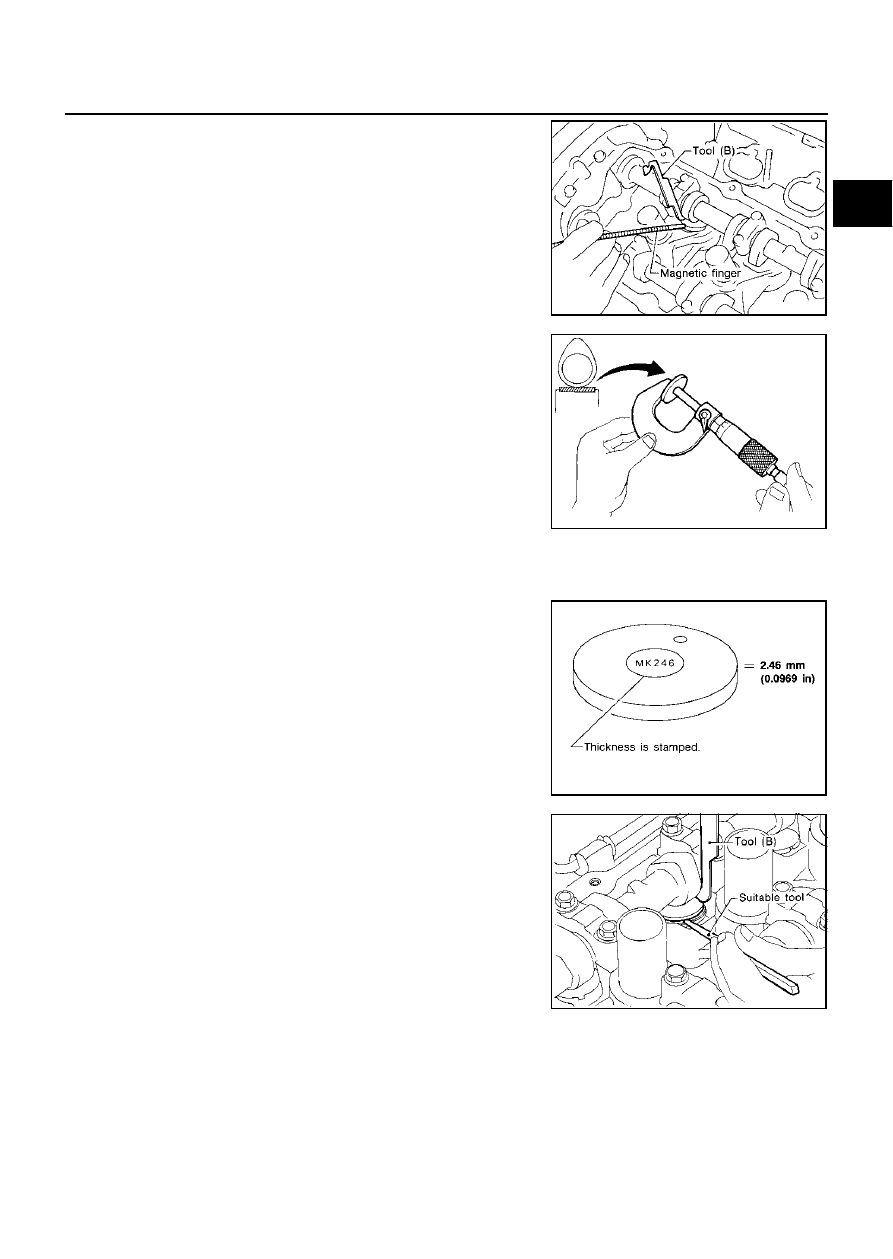
9.
Remove adjusting shim using a small screwdriver and a mag-
netic finger.
10. Determine replacement adjusting shim size following formula.
●
Using a micrometer determine thickness of removed shim
with measured at center.
●
Calculate thickness of new adjusting shim so valve clearance
comes within specified values (Cold value).
R = Thickness of removed shim
N = Thickness of new shim
M = Measured valve clearance
Shims are available in 64 sizes from 2.32 mm (0.0913 in) to 2.95 mm (0.1161 in) in steps of 0.01
mm (0.0004 in).
●
Select new shim with thickness as close as possible to calcu-
lated value.
11. Install new shim using a suitable tool.
●
Install with the surface on which the thickness is
stamped facing down.
SEM872E
Intake
: N = R + [M
−
0.30 mm (0.0118 in)]*
Exhaust
: N = R + [M
−
0.33 mm (0.0130 in)]*
*: Approximately 20
°
C (68
°
F)
SEM145D
SEM873E
SEM146D