Infiniti F50. Manual - part 540
CAMSHAFT
EM-47
C
D
E
F
G
H
I
J
K
L
M
A
EM
3.
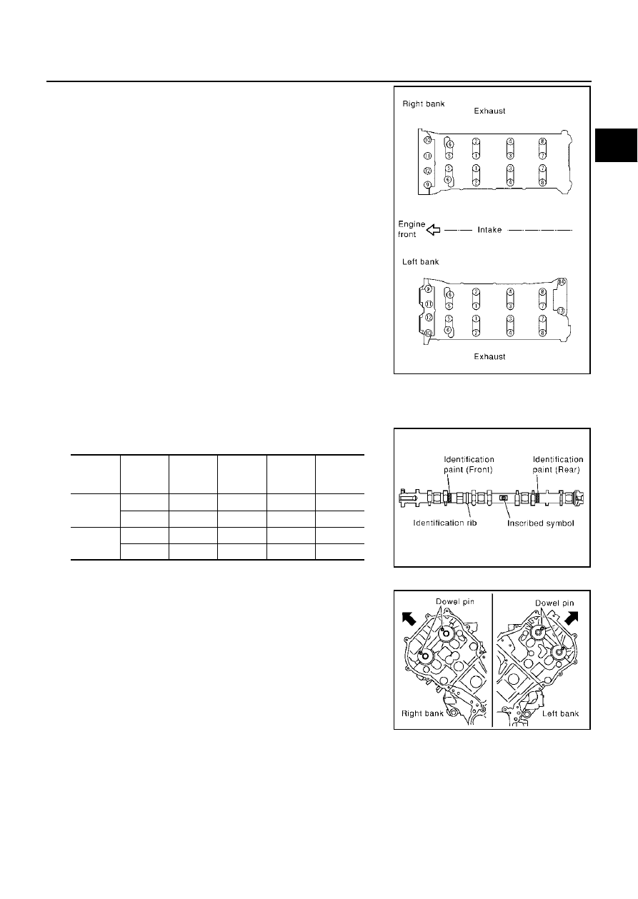
Loosen fixing bolts in the reverse order of that shown in figure to
remove camshaft brackets.
●
Lightly tapping with plastic hammer, remove No. 1 camshaft
bracket and No. 6 camshaft bracket.
NOTE:
The bottom surface of each bracket will be stuck to cylinder
head because of liquid gasket.
4.
Remove camshaft.
5.
Remove adjusting shims and valve lifters if necessary.
●
Correctly identify location where each part is installed. Keep
parts in an organized way to avoid mixing them up.
INSTALLATION
1.
Install adjusting shims and valve lifters if necessary.
●
Install removed parts in the same locations as before.
2.
Install camshafts. Refer to the table below for identification of
right and left bank, and intake and exhaust.
●
Install so that dowel pin at the front of camshaft face is in the
direction shown in the figure.
PBIC0031E
Bank
IN/EX
Identifica-
tion paint
(front)
Identifica-
tion paint
(rear)
Identifica-
tion rib
Identifica-
tion sym-
bol
LH
IN
Blue
—
No.
LH
EXH
—
Orange
No.
LH
RH
INT
Blue
—
Yes.
RH
EXH
—
Orange
Yes.
RH
PBIC0032E
SBIA0366E