Infiniti F50. Manual - part 500


  Index      Infiniti     Infiniti F50 - service repair manual 2006 year


Search            


Content   ..  498  499  500  501   ..


Infiniti F50. Manual - part 500


IGNITION SIGNAL

EC-641

C

D

E

F

G

H

I

J

K

L

M

A

EC

IGNITION SIGNAL

PFP:22448

Component Description

EBS00MNW

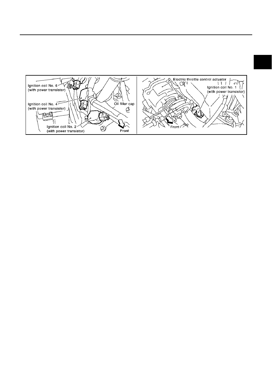
IGNITION COIL & POWER TRANSISTOR

The ignition signal from the ECM is sent to and amplified by the power transistor. The power transistor turns
ON and OFF the ignition coil primary circuit. This ON/OFF operation induces the proper high voltage in the coil
secondary circuit.

PBIB1248E

EC-642

IGNITION SIGNAL

Wiring Diagram

EBS00MNX

TBWM0167E

IGNITION SIGNAL

EC-643

C

D

E

F

G

H

I

J

K

L

M

A

EC

Specification data are reference values and are measured between each terminal and ground.
Pulse signal measured by CONSULT-II.

CAUTION:

Do not use ECM ground terminals when measuring input/output voltage. Doing so may result in dam-
age to the ECM's transistor. Use a ground other than ECM terminals, such as the ground.

TER-

MINAL 

NO.

WIRE 

COLOR

ITEM

CONDITION

DATA (DC Voltage)

12

W/L

Counter current return

[Ignition switch “ON”]

BATTERY VOLTAGE
(11 - 14V)

42

W/B

ECM relay
(Self shut-off)

[Engine is running]
[Ignition switch “OFF”]

For a few seconds after turning ignition 
switch “OFF”

0 - 1.0V

[Ignition switch “OFF”]

More than a few seconds passed after turn-
ing ignition switch “OFF”

BATTERY VOLTAGE
(11 - 14V)

163
166

R
R

Power supply for ECM

[Ignition switch “ON”]

BATTERY VOLTAGE
(11 - 14V)

EC-644

IGNITION SIGNAL

TBWM0168E


Content   ..  498  499  500  501   ..