Index Infiniti Infiniti F50 - service repair manual 2006 year
Search
Content .. 493 494 495 496 ..
Infiniti F50. Manual - part 495
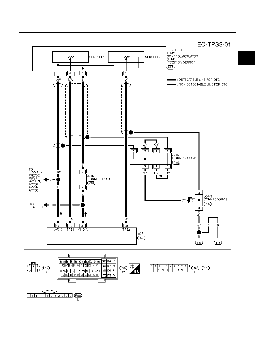
DTC P2135 TP SENSOR
EC-621
C
D
E
F
G
H
I
J
K
L
M
A
EC
Wiring Diagram
EBS00MNE
TBWM0124E