Infiniti F50. Manual - part 455
DTC P1140, P1145 IVT CONTROL POSITION SENSOR
EC-461
C
D
E
F
G
H
I
J
K
L
M
A
EC
7.
CHECK CRANKSHAFT POSITION SENSOR (POS)
Refer to
EC-314, "Component Inspection"
OK or NG
OK
>> GO TO 8.
NG
>> Replace crankshaft position sensor (POS).
8.
CHECK CAMSHAFT POSITION SENSOR (PHASE)
Refer to
EC-319, "Component Inspection"
OK or NG
OK
>> GO TO 9.
NG
>> Replace camshaft position sensor (PHASE).
9.
CHECK CAMSHAFT
Check accumulation of debris to the signal pick-up portion of the camshaft. Refer to
OK or NG
OK
>> GO TO 10.
NG
>> Remove debris and clean the signal pick-up cutout of camshaft.
10.
CHECK INTERMITTENT INCIDENT
Refer to
EC-132, "TROUBLE DIAGNOSIS FOR INTERMITTENT INCIDENT"
>> INSPECTION END
Component Inspection
EBS00MIE
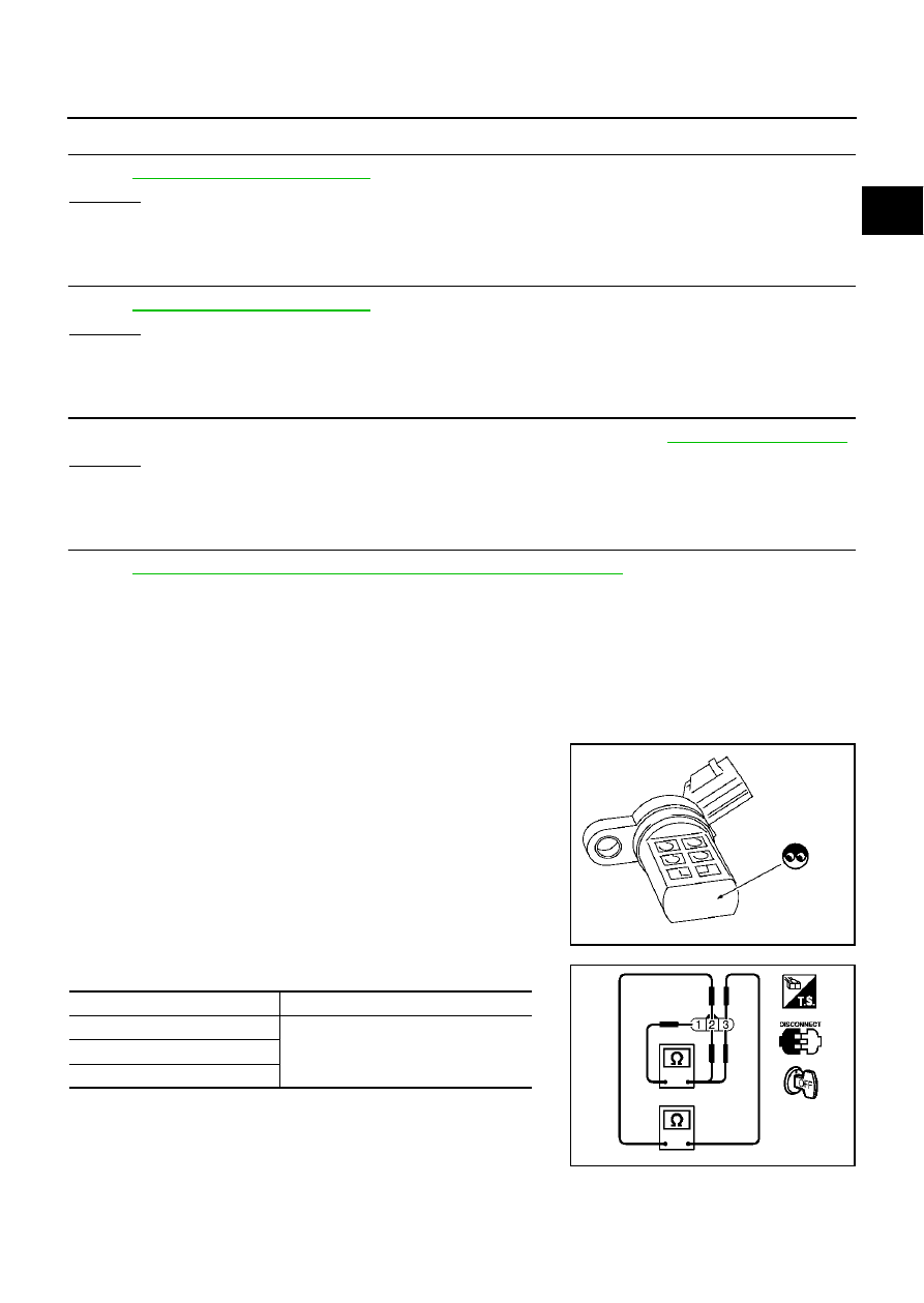
INTAKE VALVE TIMING CONTROL POSITION SENSOR
1.
Disconnect intake valve timing control position sensor harness connector.
2.
Loosen the fixing bolt of the sensor.
3.
Remove the sensor.
4.
Visually check the sensor for chipping.
5.
Check resistance as shown below.
6.
If NG, replace intake valve timing control position sensor.
SEF362Z
Terminal No. (Polarity)
Resistance
Ω
[at 25
°
C (77
°
F)]
3 (+) - 1 (-)
Except 0 or
∞
2 (+) - 1 (-)
3 (+) - 2 (-)
PBIB0194E