Infiniti F50. Manual - part 453
DTC P1128 THROTTLE CONTROL MOTOR
EC-453
C
D
E
F
G
H
I
J
K
L
M
A
EC
2.
CHECK THROTTLE CONTROL MOTOR OUTPUT SIGNAL CIRCUIT FOR OPEN OR SHORT
1.
Disconnect electric throttle control actuator harness connector.
2.
Disconnect ECM harness connector.
3.
Check harness continuity between the following terminals.
Refer to Wiring Diagram.
4.
Also check harness for short to ground and short to power.
OK or NG
OK
>> GO TO 3.
NG
>> Repair or replace.
3.
CHECK THROTTLE CONTROL MOTOR
Refer to
EC-453, "Component Inspection"
OK or NG
OK
>> GO TO 4.
NG
>> GO TO 5.
4.
CHECK INTERMITTENT INCIDENT
Refer to
EC-132, "TROUBLE DIAGNOSIS FOR INTERMITTENT INCIDENT"
OK or NG
OK
>> GO TO 5.
NG
>> Repair or replace harness or connectors.
5.
REPLACE ELECTRIC THROTTLE CONTROL ACTUATOR
1.
Replace the electric throttle control actuator.
2.
Perform
EC-46, "Accelerator Pedal Released Position Learning"
3.
Perform
EC-46, "Throttle Valve Closed Position Learning"
4.
Perform
EC-46, "Idle Air Volume Learning"
>> INSPECTION END
Component Inspection
EBS00MI6
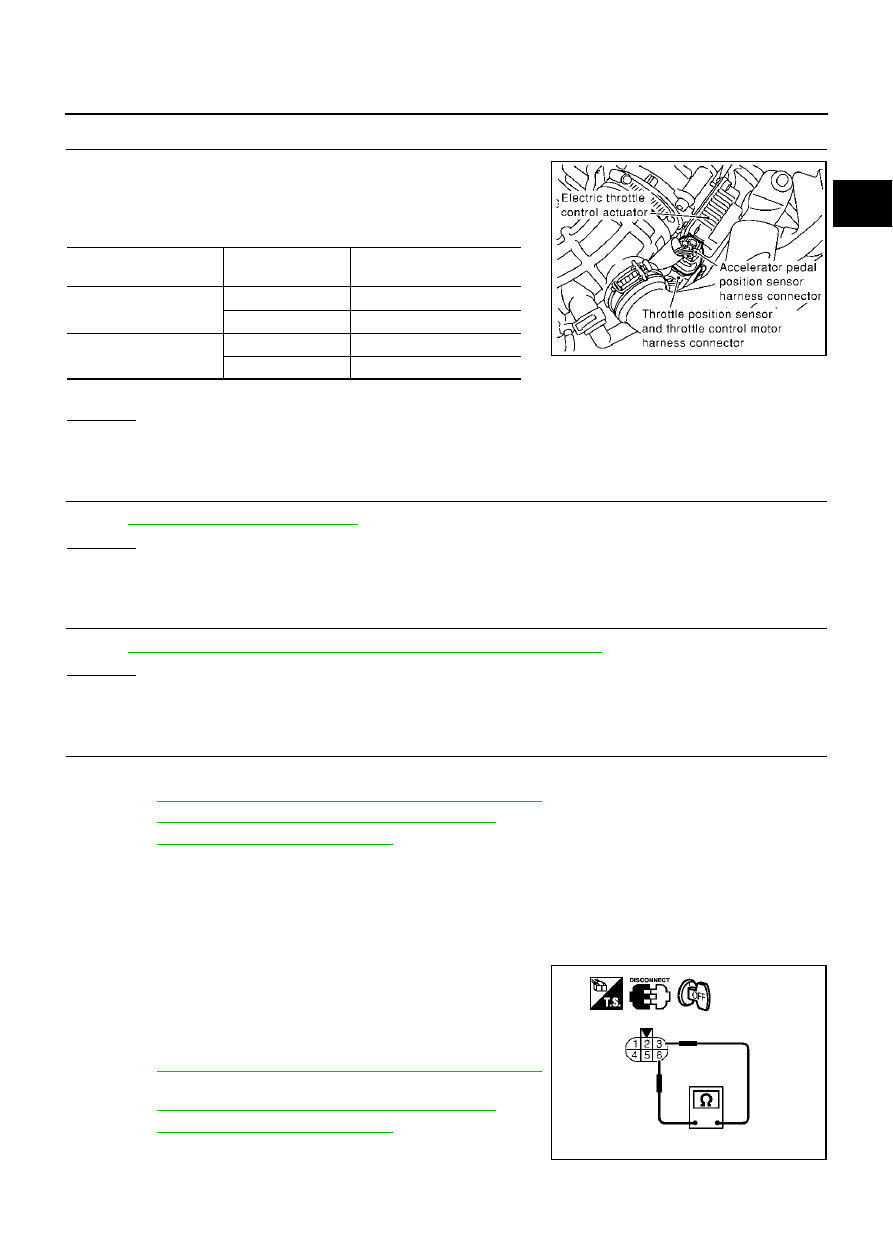
THROTTLE CONTROL MOTOR
1.
Disconnect electric throttle control actuator harness connector.
2.
Check resistance between terminals 3 and 6.
3.
If NG, replace electric throttle control actuator and go to next
step.
4.
Perform
EC-46, "Accelerator Pedal Released Position Learning"
.
5.
Perform
EC-46, "Throttle Valve Closed Position Learning"
6.
Perform
EC-46, "Idle Air Volume Learning"
Electric throttle control
actuator terminal
ECM terminal
Continuity
3
151
Should not exist
154
Should exist
6
151
Should exist
154
Should not exist
PBIB0015E
Resistance: Approximately 1 - 15
Ω
[at 25
°
C (77
°
F)]
PBIB0095E