Infiniti F50. Manual - part 370
 

  Index      Infiniti     Infiniti F50 - service repair manual 2006 year


Search            


Content   ..  368  369  370  371   ..


Infiniti F50. Manual - part 370


TROUBLE DIAGNOSIS

EC-121

C

D

E

F

G

H

I

J

K

L

M

A

EC

Generic Scan Tool (GST) Function

EBS00LW5

DESCRIPTION

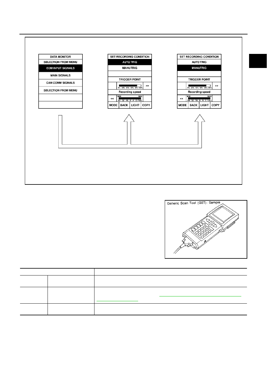
Generic Scan Tool (OBDII scan tool) complying with SAE J1978 has
8 different functions explained below.
ISO9141 is used as the protocol.
The name “GST” or “Generic Scan Tool” is used in this service man-
ual.

FUNCTION

PBIB0197E

SEF139P

Diagnostic test mode

Function

MODE 1

READINESS TESTS

This mode gains access to current emission-related data values, including analog inputs 
and outputs, digital inputs and outputs, and system status information.

MODE 2

(FREEZE DATA)

This mode gains access to emission-related data value which were stored by ECM during 
the freeze frame. For details, refer to 

EC-56, "FREEZE FRAME DATA AND 1ST TRIP 

FREEZE FRAME DATA"

 .

MODE 3

DTCs

This mode gains access to emission-related power train trouble codes which were stored 
by ECM.

EC-122

TROUBLE DIAGNOSIS

GST INSPECTION PROCEDURE

1.

Turn ignition switch OFF.

2.

Connect “GST” to data link connector, which is located under LH
dash panel near the fuse box cover.

3.

Turn ignition switch ON.

4.

Enter the program according to instruction on the screen or in
the operation manual.

(*: Regarding GST screens in this section, sample screens are
shown.)

MODE 4

CLEAR DIAG INFO

This mode can clear all emission-related diagnostic information. This includes:

●

Clear number of diagnostic trouble codes (MODE 1)

●

Clear diagnostic trouble codes (MODE 3)

●

Clear trouble code for freeze frame data (MODE 1)

●

Clear freeze frame data (MODE 2)

●

Reset status of system monitoring test (MODE 1)

●

Clear on board monitoring test results (MODE 6 and 7)

MODE 6

(ON BOARD TESTS)

This mode accesses the results of on board diagnostic monitoring tests of specific com-
ponents/systems that are not continuously monitored.

MODE 7

(ON BOARD TESTS)

This mode enables the off board test drive to obtain test results for emission-related pow-
ertrain components/systems that are continuously monitored during normal driving condi-
tions.

MODE 8

—

This mode can close EVAP system in ignition switch “ON” position (Engine stopped). 
When this mode is performed, the following parts can be opened or closed.

●

EVAP canister vent control valve open

●

Vacuum cut valve bypass valve closed

In the following conditions, this mode cannot function.

●

Low ambient temperature

●

Low battery voltage

●

Engine running

●

Ignition switch “OFF”

●

Low fuel temperature

●

Too much pressure is applied to EVAP system

MODE 9

(CALIBRATION ID)

This mode enables the off-board test device to request specific vehicle information such 
as Vehicle Identification Number (VIN) and Calibration IDs.

Diagnostic test mode

Function

PBIB0196E

SEF398S

TROUBLE DIAGNOSIS

EC-123

C

D

E

F

G

H

I

J

K

L

M

A

EC

5.

Perform each diagnostic mode according to each service proce-
dure.

For further information, see the GST Operation Manual of the
tool maker.

CONSULT-II Reference Value in Data Monitor Mode

EBS00LW6

Remarks:

●

 Specification data are reference values.

●

 Specification data are output/input values which are detected or supplied by the ECM at the connector.

* Specification data may not be directly related to their components signals/values/operations.
i.e. Adjust ignition timing with a timing light before monitoring IGN TIMING, because the monitor may show the specification data in

spite of the ignition timing not being adjusted to the specification data. This IGN TIMING monitors the data calculated by the ECM
according to the signals input from the camshaft position sensor and other ignition timing related sensors.

SEF416S

MONITOR ITEM

CONDITION

SPECIFICATION

ENG SPEED

●

Run engine and compare the CONSULT-II value with tachometer indication.

Almost the same speed as 
the tachometer indication.

MAS A/F SE-B1

●

Engine: After warming up

●

Air conditioner switch: OFF

●

Selector lever: P or N

●

No load

Idle

Approx. 1.1 - 1.5V

2,500 rpm

Approx. 1.7 - 2.4V

COOLAN TEMP/S

●

Engine: After warming up

More than 70

°

C (158

°

F)

HO2S1 (B1)
HO2S1 (B2)

●

Engine: After warming up

Maintaining engine speed at 2,000 rpm

0 - 0.3V 

←→

 Approx. 0.6 - 

1.0V

HO2S1 MNTR (B1)
HO2S1 MNTR (B2)

LEAN 

←→

 RICH

Changes more than 5 times 
during 10 seconds.

HO2S2 (B1)
HO2S2 (B2)

●

Engine: After warming up

●

After keeping engine speed 
between 3,500 and 4,000 rpm for 
1 minute and at idle for 1 minute 
under no load

Revving engine from idle up to 3,000 rpm 
quickly.

0 - 0.3V 

←→

 Approx. 0.6 - 

1.0V

HO2S2 MNTR (B1)
HO2S2 MNTR (B2)

LEAN 

←→

 RICH

VEH SPEED SE

●

Turn drive wheels and compare the CONSULT-II value with speedometer 
indication.

Almost the same speed as 
speedometer indication

BATTERY VOLT

●

Ignition switch: ON (Engine stopped)

11 - 14V

ACCEL SEN1
ACCEL SEN2*

●

Ignition switch: ON
(engine stopped)

●

Selector lever: D

Accelerator pedal: Released

More than 0.36V

Accelerator pedal: Fully depressed

Less than 4.75V

THRTL SEN1
THRTL SEN2*

●

Ignition switch: ON
(Engine stopped)

●

Selector lever: D

Accelerator pedal: Released

More than 0.36V

Accelerator pedal: Fully depressed

Less than 4.75V

EVAP SYS PRES

●

Ignition switch: ON

Approx. 1.8 - 4.8V

START SIGNAL

●

Ignition switch: ON 

→

 START 

→

 ON

OFF 

→

 ON 

→

 OFF

CLSD THL POS

●

Ignition switch: ON
(Engine stopped)

●

Selector lever: D

Accelerator pedal: Fully released

ON

Accelerator pedal: Slightly depressed

OFF

AIR COND SIG

●

Engine: After warming up, idle 
the engine

Air conditioner switch: OFF

OFF

Air conditioner switch: ON
(Compressor operates.)

ON

EC-124

TROUBLE DIAGNOSIS

P/N POSI SW

●

Ignition switch: ON

Selector lever: P or N

ON

Selector lever: Except above

OFF

PW/ST SIGNAL

●

Engine: After warming up, idle 
the engine

Steering wheel is in neutral position.
(Forward direction)

OFF

Steering wheel is turned.

ON

LOAD SIGNAL

●

Ignition switch: ON

Rear window defogger switch is ON and/
or lighting switch is in 2nd.

ON

Rear window defogger switch is OFF and 
lighting switch is OFF.

OFF

IGNITION SW

●

Ignition switch: ON 

→

 OFF 

→

 ON

ON 

→

 OFF 

→

 ON

HEATER FAN SW

●

Engine: After warming up, idle 
the engine

Heater fan is operating.

ON

Heater fan is not operating

OFF

BRAKE SW

●

Ignition switch: ON

Brake pedal: Fully released

OFF

Brake pedal: Slightly depressed

ON

INJ PULSE-B1
INJ PULSE-B2

●

Engine: After warming up

●

Selector lever: P or N

●

Air conditioner switch: OFF

●

No load

Idle

2.0 - 3.0 msec

2,000 rpm

1.9 - 2.9 msec

B/FUEL SCHDL

●

Engine: After warming up

●

Selector lever: P or N

●

Air conditioner switch: OFF

●

No load

Idle

2.3 - 2.9 msec

2,000 rpm

2.3 - 2.9 msec

IGN TIMING

●

Engine: After warming up

●

Selector lever: P or N

●

Air conditioner switch: OFF

●

No load

Idle

10

°

 - 18

°

 BTDC

2,000 rpm

25

°

 - 45

°

 BTDC

A/F ALPHA-B1
A/F ALPHA-B2

●

Engine: After warming up

Maintaining engine speed at 2,000 rpm

54% - 155%

CAL/LD VALUE

●

Engine: After warming up

●

Selector lever: P or N

●

Air conditioner switch: OFF

●

No load

Idle

15% - 35%

2,500 rpm

10% - 35%

MASS AIRFLOW

●

Engine: After warming up

●

Selector lever: P or N

●

Air conditioner switch: OFF

●

No load

Idle

3.8 - 5.2 g·m/s

2,500 rpm

16.0 - 21.5 g·m/s

PURG VOL C/V

●

Engine: After warming up

●

Selector lever: P or N

●

Air conditioner switch: OFF

●

No load

Idle

0%

2,000 rpm

—

INT/V TIM (B1)
INT/V TIM (B2)

●

Engine: After warming up

●

Selector lever: P or N

●

Air conditioner switch: OFF

●

No load

Idle

−

5

°

 - 5

°

CA

2,000 rpm

Approx. 0

°

 - 20

°

CA

INT/V SOL (B1)
INT/V SOL (B2)

●

Engine: After warming up

●

Selector lever: P or N

●

Air conditioner switch: OFF

●

No load

Idle

0% - 2%

2,000 rpm

Approx. 25% - 50%

MONITOR ITEM

CONDITION

SPECIFICATION


Content   ..  368  369  370  371   ..