Infiniti F50. Manual - part 338
VOICE ACTIVATED CONTROL SYSTEM
DI-195
C
D
E
F
G
H
I
J
L
M
A
B
DI
Voice Command Not Identified (With Voice Activated Control System in Opera-
tion)
EKS001B0
1.
CHECK MICROPHONE OPERATION
1.
Select “Voice Mic. Test” of “CONFIRMATION/ADJUSTMENT” mode. Refer to
2.
Speak to microphone, and check if the sound is heard from (right) instrument speaker.
OK or NG
OK
>> Replace voice activated control module.
NG
>> GO TO 2.
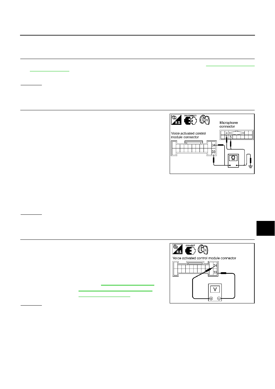
2.
CHECK MICROPHONE CIRCUIT
1.
Disconnect voice activated control module connector and micro-
phone connector.
2.
Check the following.
●
Continuity between voice activated control module harness con-
nector B69 terminal 33 (L) and microphone connector R10 ter-
minal 5 (L).
●
Continuity between voice activated control module harness con-
nector B69 terminal 34 (R/W) and microphone harness connec-
tor R10 terminal 4 (R).
●
Continuity between voice activated control module harness connector B69 terminal 33 (L), 34 (R/W) and
ground.
OK or NG
OK
>> GO TO 3.
NG
>> Repair harness or connector.
3.
CHECK MICROPHONE SIGNAL
1.
Connect voice activated control module connector and micro-
phone connector.
2.
Turn ignition switch ON.
3.
Speak to microphone and check signal between voice activated
control module connector B69 terminal 34 (R/W) and 33 (L) with
CONSULT-II or oscilloscope.
OK or NG
OK
>> Replace voice activated control module.
NG
>> Replace microphone.
Continuity should exist.
Continuity should exist.
Continuity should not exist.
SKIA4152E
34 (R/W) - 33 (L)
: Refer to
Reference Values for Voice Acti-
vated Control Module"
SKIA4116E