Infiniti F50. Manual - part 314
VEHICLE INFORMATION AND INTEGRATED SWITCH SYSTEM /WITHOUT
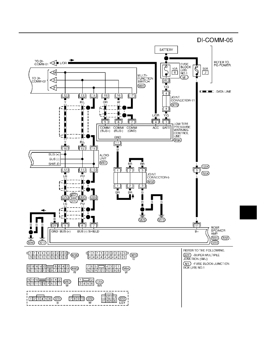
NAVIGATION SYSTEM
DI-99
C
D
E
F
G
H
I
J
L
M
A
B
DI
TKWM0299E
|
|
|
VEHICLE INFORMATION AND INTEGRATED SWITCH SYSTEM /WITHOUT NAVIGATION SYSTEM DI-99 C D E F G H I J L M A B DI TKWM0299E |