Infiniti F50. Manual - part 263


  Index      Infiniti     Infiniti F50 - service repair manual 2006 year


Search            


Content   ..  261  262  263  264   ..


Infiniti F50. Manual - part 263


REAR DISC BRAKE

BR-33

C

D

E

G

H

I

J

K

L

M

A

B

BR

CAUTION:

Do not reuse copper washer for union bolts.

Assemble brake hose securely to protrusion on caliper assembly.

4.

After installing caliper assembly, refill with new brake fluid and bleed air.

Caliper Disassembly and Assembly 

EFS000NR

DISASSEMBLY 

1.

Remove caliper assembly from vehicle.

2.

Remove sliding pins. Then remove pads, shims, and shim cov-
ers from caliper assembly, and remove pad retainers from cylin-
der body.

3.

Remove sliding pin boot from torque member.
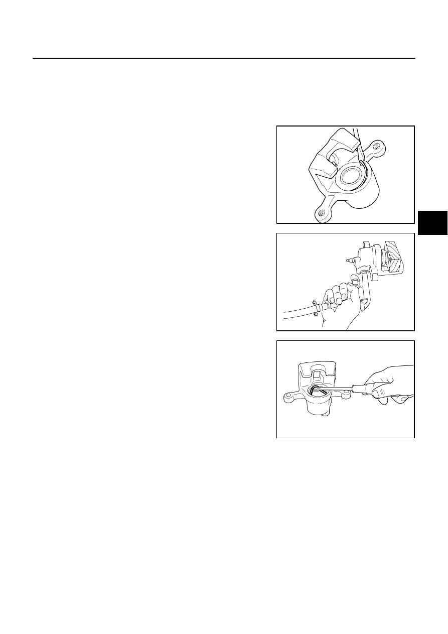
4.

Using a flat-bladed screwdriver as shown in figure, remove
retaining ring from cylinder body.

5.

Place a wooden block as shown in figure, and blow air from
union bolt mounting hole to remove pistons and piston boots.

6.

Using a flat-bladed screwdriver, remove piston seals from cylin-
der body.

CAUTION:

Be careful not to damage inner wall of cylinder.

INSPECTION AFTER DISASSEMBLY 
Cylinder Body

CAUTION:

Use new brake fluid to clean. Never use mineral oils such as gasoline or kerosene.

Check inner wall of cylinder for corrosion, wear, and damage. If a failure is detected, replace cylinder
body.

Minor flaws caused by corrosion or foreign material can be removed by polishing the surface with a fine
sandpaper. Replace cylinder body, if necessary.

Torque Member

Check for wear, cracks, and damage. If a malfunction is detected, replace applicable part.

Piston

CAUTION:

The piston sliding surface is plated. Do not polish with sandpaper.
Check piston surface for corrosion, wear, and damage. If a malfunction is detected, replace applicable part.

SBR028A

BRD0041D

SFIA0999E

BR-34

REAR DISC BRAKE

Sliding Pin, Pin Bolt and Pin Boot

Check sliding pin and sliding pin boot for wear, damage, and cracks. If a malfunction is detected, replace appli-
cable part.

DISC ROTOR INSPECTION 
Visual Inspection

Check surface of disc rotor for uneven wear, cracks, and serious damage. If a malfunction is detected, replace
applicable part.

Run Out Inspection

1.

Using wheel nuts, fix the disc rotor to wheels hub. (2 or more positions)

2.

Using a dial indicator, check run out.

CAUTION:

Before measuring, make sure that axle end play is 0 mm.

3.

If run out is outside limit, find minimum run out point by shifting
mounting positions of disc rotor and wheel hub by one hole.

Thickness Inspection

Using a micrometer, check thickness of disc rotor. If thickness is out-
side standard, replace disc rotor.

ASSEMBLY 

1.

Apply brake fluid to piston seals and install them to cylinder
body.

CAUTION:

Do not reuse piston seals.

2.

Apply brake fluid to piston boots. Cover the piston end with pis-
ton boot, and install cylinder-side lip on piston boots properly
into groove on cylinder body.

CAUTION:

Do not reuse piston boot.

3.

Press piston into cylinder body by hand to assemble piston-side
lip on piston boot properly into groove on piston.

CAUTION:

Press the piston evenly and change the pressing point to
prevent inner wall of cylinder from being rubbed.

Measure-
ment point

: At a point 10 mm (0.39 in) from 
outer edge of disc.

Maximum 
run out

: 0.07 mm (0.0028 in) or less

BRA0013D

Standard thickness

: 16.0 mm (0.63 in)

Wear limit

: 14.0 mm (0.55 in)

Maximum uneven wear 
(measured at 8 posi-
tions)

; 0.015 mm (0.0006 in) 
or less

SBR020B

SFIA0156E

SFIA0157E

REAR DISC BRAKE

BR-35

C

D

E

G

H

I

J

K

L

M

A

B

BR

4.

Fix the piston boot with retaining ring.

CAUTION:

Make sure that boot is securely engaged in groove on
cylinder body.

Do not reuse retaining ring.

5.

Install sliding pins and sliding pin boots to torque member.

6.

Install torque member to axle assembly, and tighten mounting
bolts to the specified torque.

CAUTION:

Before installing torque member to axle assembly, wipe oil
and grease on washer seats on axle assembly and mount-
ing surface of torque member.

7.

Install pad retainers to torque member.

8.

After assembling shims and shim covers to pads, assemble it to torque member.

9.

Install cylinder body, and tighten sliding pin bolts to the specified torque.

10. Install brake hose to cylinder body and tighten union bolts to the specified torque.

CAUTION:

Assemble brake hose securely to protrusions on cylinder body.

Do not reuse copper washer on union bolt.

11. After installing caliper assembly, refill new brake fluid and bleed air.

SFIA0158E

BR-36

SERVICE DATA AND SPECIFICATIONS (SDS)

SERVICE DATA AND SPECIFICATIONS (SDS)

PFP:00030

General Specifications

EFS000O9

Unit: mm (in)

Brake Pedal

EFS000GJ

Check Valve

EFS000GK

Brake Booster

EFS000GL

Vacuum type

Front Disc Brake

EFS000GM

Rear Disc Brake

EFS000GN

Front brake

Brake model

CLZ31VA

Cylinder bore diameter

42.86 (1.687) 

×

 2

Pad
Length 

×

 width 

×

 thickness

127.0 

×

 56.0 

×

 10.0

(5.00 

×

 2.20 

×

 0.394)

Rotor outer diameter 

×

 thickness

290 

×

 28 (11.42 

×

 1.10)

Rear brake 

Brake model

AD14VD

Cylinder bore diameter

43.86 (1.727)

Pad
Length 

×

 width 

×

 thickness

97.4 

×

 33.9 

×

 9.8

(3.835 

×

 1.335 

×

 0.386)

Rotor outer diameter 

×

 thickness

292 

×

 16 (11.50 

×

 0.63)

Master cylinder

Cylinder bore diameter

25.4 (1 in)

Control valve

Valve model

Electric brake force distribution

Brake booster

Booster model

M215T

Diaphragm diameter

Primary

230 (9.06)

Secondary

205 (8.07)

Recommended brake fluid

DOT 3

Free play (at pedal top surface)

3 - 11 mm (0.12 - 0.43 in)

Brake pedal height (from dash panel top surface)

192.4 - 202.4 mm (7.57 - 7.97 in)

Depressed pedal height under force of 490 N (50 kg, 110 lb)
(from dash panel top surface)

90 mm (3.54 in) or more

Clearance between stopper rubber and threaded end of stop 
lamp switch/ASCD cancel switch

0.74 - 1.96 mm (0.0291 - 0.0772 in)

Vacuum leakage 
[at vacuum of – 66.7 kPa (– 500 mmHg, – 19.69 inHg)]

Within 1.3 kPa (10 mmHg, 0.39 inHg) of Vacuum for 15 seconds

Vacuum leakage 
[at vacuum of – 66.7 kPa (– 500 mmHg, –19.69 inHg)]

Within 3.3 kPa (25 mmHg, 0.98 inHg) of vacuum for 15 seconds

Input rod installation standard dimension

125 mm (4.92 in)

Brake type

CLZ31VA

Brake pad

Standard thickness (new)

10.0 mm (0.394 in)

Repair limit thickness

2.0 mm (0.079 in)

Disc rotor

Standard thickness (new)

28.0 mm (1.10 in)

Repair limit thickness

26.0 mm (1.02 in)

Maximum run out

0.05 mm (0.002 in) or less

Brake type

AD14VD

Brake pad

Standard thickness (new)

9.8 mm (0.386 in)

Repair limit thickness

2.0 mm (0.079 in)


Content   ..  261  262  263  264   ..