Infiniti F50. Manual - part 261
FRONT DISC BRAKE
BR-25
C
D
E
G
H
I
J
K
L
M
A
B
BR
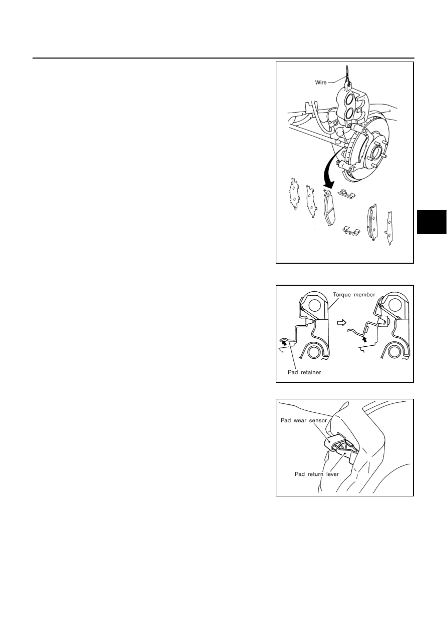
3.
Hang cylinder body with a wire, and remove pads, pad retainers,
shims from torque member.
CAUTION:
●
When removing pad retainer from torque member, lift pad
retainer in the direction shown by arrow (shown in the
figure) so as not to deform it.
●
Do not damage piston boot.
●
Keep brake fluid clean of rotor.
INSTALLATION
1.
Apply brake grease to the back of pad and both sides of shim,
install inner shim to inner pad, and outer shim and outer shim
cover to outer pad.
2.
Apply disc brake grease to pad contact surface on pad retainer,
and install pad retainers and pads to torque member.
CAUTION:
The CLZ31VA inner pad and outer pad have pad-return
mechanism on upper side of pad retainer. When installing
CLZ31VA pad to torque member, be sure to install pad
return lever to pad wear sensor securely.
3.
Install cylinder body to torque member.
CAUTION:
When replacing pads with new ones, press in piston until pads can be installed. In this case, care-
fully monitor brake fluid level in reservoir tank because brake fluid will return to reservoir tank of
master cylinder.
SBR040C
SBR556E
SBR557E