Infiniti F50. Manual - part 234


  Index      Infiniti     Infiniti F50 - service repair manual 2006 year


Search            


Content   ..  232  233  234  235   ..


Infiniti F50. Manual - part 234


VEHICLE SECURITY (THEFT WARNING) SYSTEM

BL-183

C

D

E

F

G

H

J

K

L

M

A

B

BL

Diagnostic Procedure 7

EIS003QH

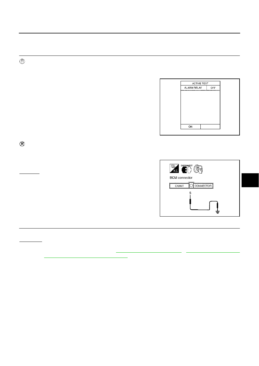
CHECK THEFT WARNING HEADLAMP ALARM

1. 

CHECK VEHICLE SECURITY HEADLAMP ALARM OPERATION

 With CONSULT-II

Check headlamp relay “ALARM RELAY” in “ACTIVE TEST” mode with CONSULT-II.

Perform operation shown on display.

 Without CONSULT-II

1.

Disconnect BCM connector.

2.

Apply ground to BCM connector M4 terminal 5 (R/Y). 

OK or NG

OK

>> Headlamp alarm is OK.

NG

>> GO TO 2.

2. 

CHECK HEADLAMP RELAY 1 AND 2

Does headlamp come on when turning lighting switch “ON”?

YES or NO

YES

>> Check harness for open or short between each headlamp relay and BCM.

NO

>> Check headlamp system. Refer to 

LT-6, "HEADLAMP (FOR USA)"

 , 

LT-37, "HEADLAMP (FOR

CANADA) - DAYTIME LIGHT SYSTEM -"

 .

Theft warning headlamp alarm should operate.

PIIA0362E

Does headlamp alarm activate?

PIIA0363E

BL-184

VEHICLE SECURITY (THEFT WARNING) SYSTEM

Diagnostic Procedure 8

EIS0043K

CHECK ACC POWER SUPPLY

1. 

CHECK ACC POWER

 With CONSULT-II

Check ACC power (“ACC ON SW”) in “DATA MONITOR” mode with CONSULT-II.

Without CONSULT-II

Check voltage between BCM connector and ground.

OK or NG

OK

>> ACC power is OK.

NG

>> Check the following.

10A fuse [No. 21, located in fuse block (J/B) No.1]

Harness for open or short between BCM and fuse

Monitor item

Condition

ACC ON SW

Ignition switch ACC or ON position

: ON

Ignition switch OFF position

: OFF

PIIA3367E

Item

Connector

Terminal

(Wire color)

Condition

Voltage (V)

(Approx.)

( + )

( – )

BCM

M4

60 (L/OR)

Ground

ACC or ON

Battery voltage

OFF

0

PIIA3438E

ELECTRONIC KEY SYSTEM

BL-185

C

D

E

F

G

H

J

K

L

M

A

B

BL

ELECTRONIC KEY SYSTEM

PFP:80561

Component Parts and Connector Location

EIS000O4

System Description

EIS000O3

Every electronic key (including transponder) has its own key ID No. However, only an electronic key with
the key ID registered in the NATS IMMU and ECM can turn ON while inserted in the ignition key cylinder,
allowing the engine to start.

An ignition key (electronic key) with straight contour is adopted to prevent the electronic key from vehicle
theft by abuse of duplicated key etc.

If the batteries for the vehicle and handheld transmitter are discharged, using the emergency key inte-
grated into the electronic key, the driver/passenger doors and trunk lid can be operated for open/close,
and the steering wheel lock can be unlocked.

NOTE:
The engine cannot be started with an emergency key.

If any of ECM, NATS IMMU, steering lock control unit (integrated in the key cylinder) or ignition key (elec-
tronic key) has been replaced, or if the trouble diagnosis requires additional registration, mandatory re-
registration procedure and registration of the electronic key ID code (if an ignition-key is added) are
required.

NOTE:
All the keys kept by the vehicle owner re-registration of the key ID (electronic key) shall be necessary.

If the vehicle owner requires, electronic key ID codes can be registered for up to four keys (including the
electronic key). In this case, the key IDs shall also be registered.

NOTE:

The key ID code and remote controller ID code for the key equipped on the vehicle have already been
registered at factory.

When conducting registration of key ID for repair, part replacement, and electronic key addition, even the
registered ignition (standard) key shall be registered again. Therefore, collect all the keys from the vehicle
owner.

PIIA3359E

BL-186

ELECTRONIC KEY SYSTEM

SECURITY INDICATOR

OUTLINE OF ELECTRONIC KEY OPERATION
Operation 1 (Insert the key into the ignition key cylinder.)

1.

By inserting the ignition key (electronic key: built-in transponder) into the key cylinder, the key detection
switch is turned to ON.

2.

The power is supplied from the NATS IMMU 

 NATS antenna amp. 

 antenna coil.

3.

The current through the antenna coil induces a magnetic field.

4.

The coil in the transponder induces electromotive force by mutual induction, which is charged in the
capacitor.

5.

The transponder uses the charged energy to transmit the built-in key ID signal.

6.

The sent key ID signal is received by the antenna coil and transmitted via the NATS antenna amp. to
NATS IMMU.

7.

NATS IMMU compares the stored key ID and received one, and only if the matching result is OK, it trans-
mits the key rotation permission signal to the steering lock control unit (integrated in the key cylinder).

8.

When the key rotation permission signal is input, the steering lock control unit activates the electronic key
solenoid valve in the key cylinder to allow the electronic key to turn.

9.

Turn ignition switch ON.

10. Only if the key ID matching result is OK, the ECM allows the engine to start.

Operation 2 (Withdraw the key from the ignition key cylinder.)

1.

Return the electronic key to the LOCK position of the steering system lock.

2.

When the key is removed, the electronic key solenoid valve in the key cylinder returns to inhibit the key
from turning. In this case, the steering lock control unit processes the key switch ON 

 OFF signal by

itself to inhibit the electronic key from turning.

NOTE:
If the A/T selector lever is not in “P” position, the electronic key does not return to LOCK position.

Condition of secu-
rity indicator

Key

Operation or condition

Ignition switch: ON 
position

Ignition switch: ACC 
position

Ignition switch: OFF 
position (electronic 
key is inserted.)

Ignition switch: OFF 
position (electronic 
key is not inserted.)

Electronic key

Lamp OFF

Lamp OFF

Lamp OFF

Blinking

Emergency key

ON

ON

ON

Blinking

PIIA0376E


Content   ..  232  233  234  235   ..