Infiniti F50. Manual - part 146
TROUBLE DIAGNOSIS
ATC-109
C
D
E
F
G
H
I
K
L
M
A
B
ATC
2.
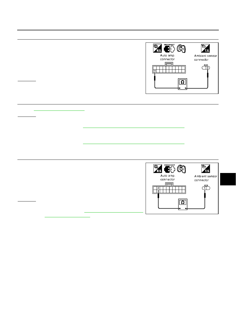
CHECK CIRCUIT CONTINUITY BETWEEN AMBIENT SENSOR AND AUTO AMP.
1.
Turn ignition switch OFF.
2.
Disconnect auto amp. connector.
3.
Check continuity between ambient sensor harness connector
E58 terminal 2 (R/Y) and auto amp. harness connector M119
terminal 11 (R/Y).
OK or NG
OK
>> GO TO 3.
NG
>> Repair harness or connector.
3.
CHECK AMBIENT SENSOR
Refer to
OK or NG
OK
>> 1. Replace auto amp.
2. Go to self-diagnosis
ATC-54, "FUNCTION CONFIRMATION PROCEDURE"
and perform self-
diagnosis STEP-2. Confirm that code No. 20 is displayed.
NG
>> 1. Replace ambient sensor.
2. Go to self-diagnosis
ATC-54, "FUNCTION CONFIRMATION PROCEDURE"
and perform self-
diagnosis STEP-2. Confirm that code No. 20 is displayed.
4.
CHECK CIRCUIT CONTINUITY BETWEEN AMBIENT SENSOR AND AUTO AMP.
1.
Turn ignition switch OFF.
2.
Disconnect auto amp. connector.
3.
Check continuity between ambient sensor harness connector
E58 terminal 1 (G/R) and auto amp. harness connector M119
terminal 2 (G/R).
OK or NG
OK
>> 1. Replace auto amp.
2. Go to self-diagnosis
STEP-2. Confirm that code No. 20 is displayed.
NG
>> Repair harness or connector.
2 – 11
: Continuity should exist.
RJIA0245E
1 – 2
: Continuity should exist.
RJIA0246E