Infiniti F50. Manual - part 145
TROUBLE DIAGNOSIS
ATC-105
C
D
E
F
G
H
I
K
L
M
A
B
ATC
No A/C Display is Shown
EJS001YB
1.
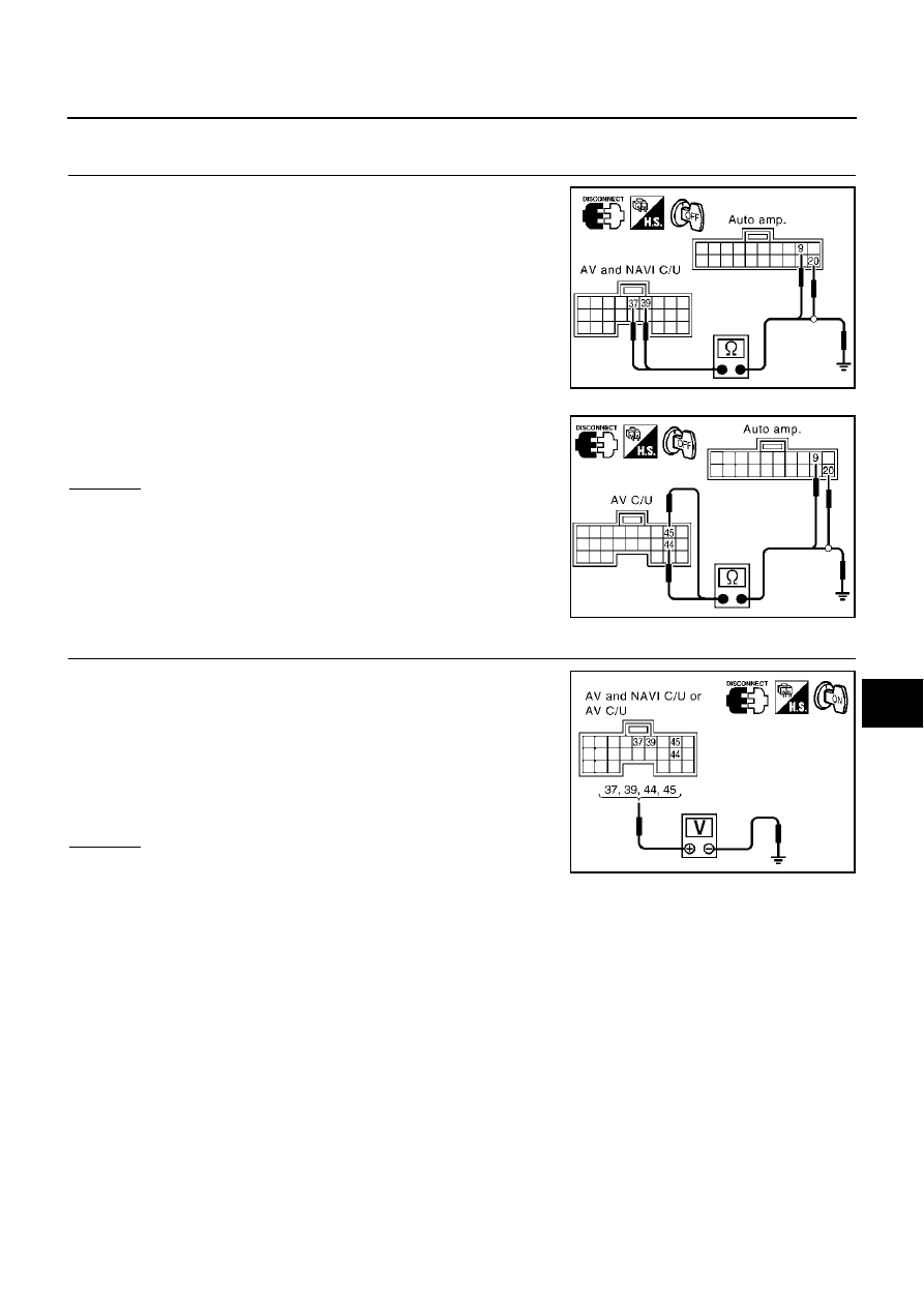
CHECK CIRCUIT CONTINUITY BETWEEN AV (AND NAVI) CONTROL UNIT AND AUTO AMP.
1.
Disconnect auto amp. connector and AV and NAVI control unit
or AV control unit connector.
2.
Check continuity between AV and NAVI control unit harness
connector B29 terminals 37 (W), 39 (B) or AV control unit har-
ness connector M77 terminals 44 (W), 45 (B) and ground.
3.
Check continuity between AV and NAVI control unit harness
connector B29 terminals 37 (W), 39 (B) or AV control unit har-
ness connector M77 terminals 44 (W), 45 (B) and auto amp.
harness connector M119 terminals 9 (W), 20 (B).
OK or NG
OK
>> GO TO 2.
NG
>>
●
Check harness between auto amp. and AV and NAVI
control unit or AV control unit.
●
Check connector housings for disconnected or loose
terminals.
2.
A/C–AV, AC–CLK COMMUNICATION SIGNAL CHECK
1.
Reconnect auto amp. connector.
2.
Turn the ignition switch ON.
3.
Check voltage between AV and NAVI control unit harness con-
nector B29 terminals 37 (W), 39 (B) or AV control unit harness
connector M77 terminals 44 (W), 45 (B) and ground.
OK or NG
OK
>> GO TO 3.
NG
>> Replace auto amp.
37, 39 – Ground
: Continuity should not exist.
44, 45 – Ground
: Continuity should not exist.
37, 44 – 9
: Continuity should exist.
39, 45 – 20
: Continuity should exist.
RJIA1576E
RJIA1577E
37, 39 – Ground
: Approx. 3.5V or more
44, 45 – Ground
: Approx. 3.5V or more
RJIA1578E