Infiniti F50. Manual - part 102
ON-VEHICLE SERVICE
AT-293
D
E
F
G
H
I
J
K
L
M
A
B
AT
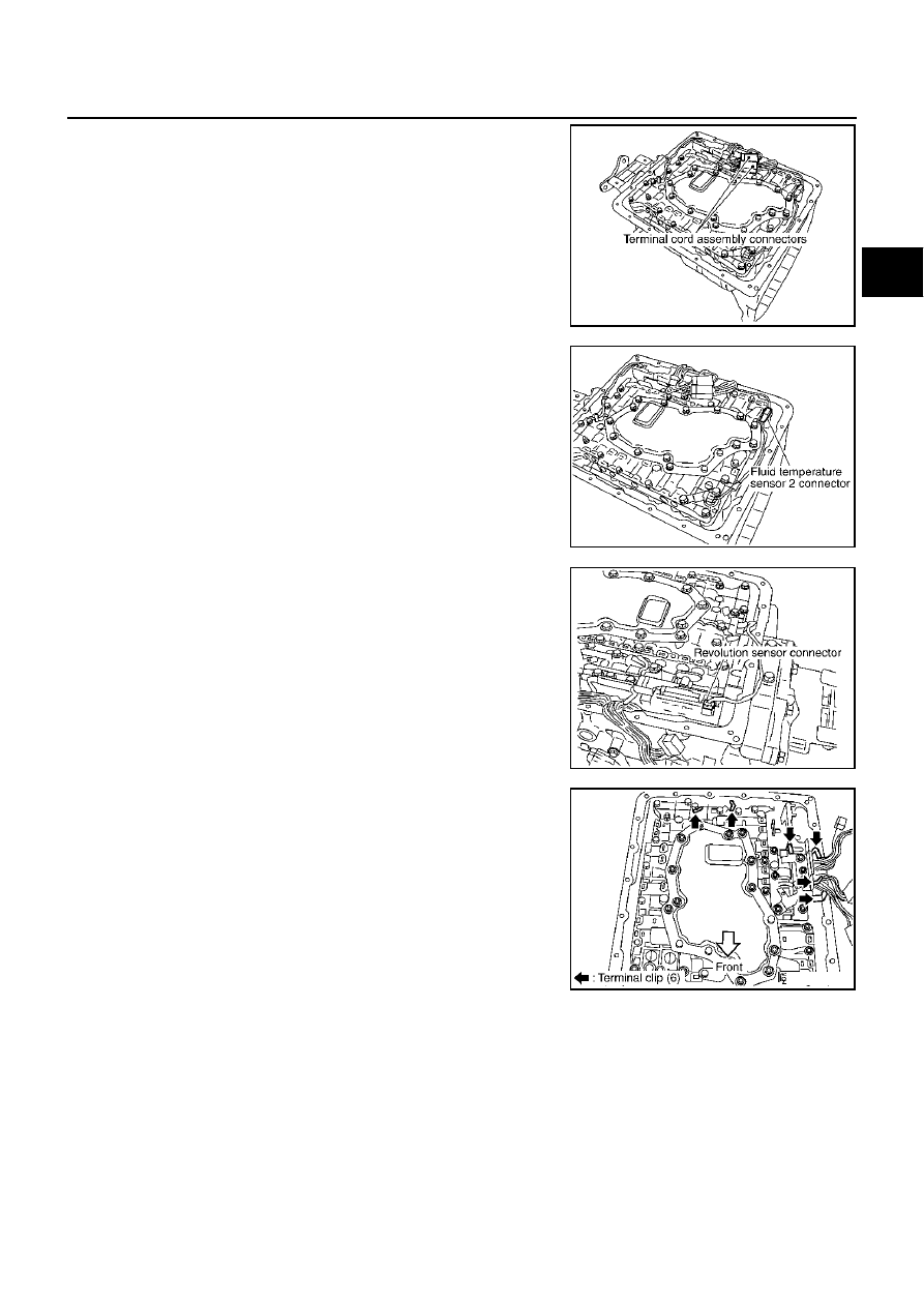
5.
Connect terminal cord assembly connectors.
6.
Connect fluid temperature sensor 2 connector.
7.
Connect revolution sensor connector.
8.
Securely fasten terminal harness with clip.
9.
Install oil pan in transmission case.
a.
Install oil pan gasket in transmission case.
CAUTION:
●
Do not reuse oil pan gasket.
●
Install it in the direction to align hole positions.
SCIA2309E
SCIA2581E
SCIA2313E
SCIA2314E