Infiniti F50. Manual - part 101


  Index      Infiniti     Infiniti F50 - service repair manual 2006 year


Search            


Content   ..  99  100  101  102   ..


Infiniti F50. Manual - part 101


ON-VEHICLE SERVICE

AT-289

D

E

F

G

H

I

J

K

L

M

A

B

AT

ON-VEHICLE SERVICE

PFP:00000

Control Valve Assembly

ECS00BFP

CAUTION:

When replacing the control valve assembly, erase EEP ROM in TCM. Refer to 
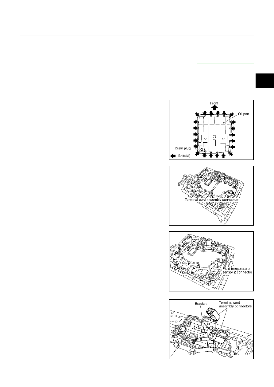
AT-8, "Precautions for A/

T Assembly Replacement"

 .

REMOVAL

1.

Disconnect the negative battery terminal

2.

Disconnect heated oxygen sensor 2 harness connector.

3.

Drain ATF through drain plug.

4.

Remove oil pan and oil pan gasket.

5.

Disconnect terminal cord assembly connectors.

CAUTION:

Be careful not to damage connector.

6.

Disconnect fluid temperature sensor 2 connector.

CAUTION:

Be careful not to damage connector.

7.

Remove terminal cord assembly connectors from bracket.

CAUTION:

Be careful not to damage connector.

SCIA2308E

SCIA2309E

SCIA2581E

SCIA2584E

AT-290

ON-VEHICLE SERVICE

8.

Disconnect revolution sensor connector.

CAUTION:

Be careful not to damage connector.

9.

Straighten terminal clips to free terminal cord assembly and rev-
olution sensor harness then remove terminal clips.

CAUTION:

Hang down terminal cord assembly and revolution sensor
harness toward outside so as not to disturb removal of con-
trol valve assembly.

10. Remove bolts A, B and C from control valve assembly.

11. Remove control valve assembly from transmission case.

CAUTION:

When removing, be careful with the manual valve notch and
manual plate height.  Remove it vertically.

12. Remove fluid temperature sensor 2 with bracket from control

valve assembly.

SCIA2313E

SCIA2314E

Bolt symbol

Length mm (in)

Number of bolts

A

42 (1.65)

5

B

55 (2.17)

6

C

40 (1.57)

1

SCIA2312E

SCIA2315E

SCIA2582E

ON-VEHICLE SERVICE

AT-291

D

E

F

G

H

I

J

K

L

M

A

B

AT

13. Remove bracket from fluid temperature sensor 2.

INSTALLATION

1.

Install fluid temperature sensor 2 in bracket.

2.

Install fluid temperature sensor 2 in control valve assembly.
(With bracket.)

3.

Install control valve assembly.

a.

Install control valve assembly in transmission case.

CAUTION:

Hang down terminal cord assembly and revolution sensor harness toward outside so as not to
disturb installation of control valve assembly.

Make sure that turbine sensor securely installs turbine sensor hole.

SCIA2583E

SCIA2813E

: 6.9 - 8.8 N·m (0.71 - 0.89 kg-m, 61 - 77 in-lb)

SCIA2582E

SCIA2315E

AT-292

ON-VEHICLE SERVICE

Assemble it so that manual valve cutout is engaged with
manual plate projection.

b.

Install bolts A, B and C in control valve assembly.

c.

Tighten bolt 1, 2 and 3 temporarily to prevent dislocation.  After
that tighten them in order (1 

 2 

 3), and then tighten other

bolts.

4.

Install terminal cord assembly connectors in bracket.

SCIA2812E

Bolt symbol

Length mm (in)

Number of bolts

A

42 (1.65)

5

B

55 (2.17)

6

C

40 (1.57)

1

SCIA2312E

: 6.9 - 8.8 N·m (0.71 - 0.89 kg-m, 61 - 77 in-lb)

SCIA3170E

SCIA2584E


Content   ..  99  100  101  102   ..