Infiniti F50. Manual - part 88


  Index      Infiniti     Infiniti F50 - service repair manual 2006 year


Search            


Content   ..  86  87  88  89   ..


Infiniti F50. Manual - part 88


TROUBLE DIAGNOSIS FOR SYMPTOMS

AT-237

D

E

F

G

H

I

J

K

L

M

A

B

AT

TROUBLE DIAGNOSIS FOR SYMPTOMS

PFP:00007

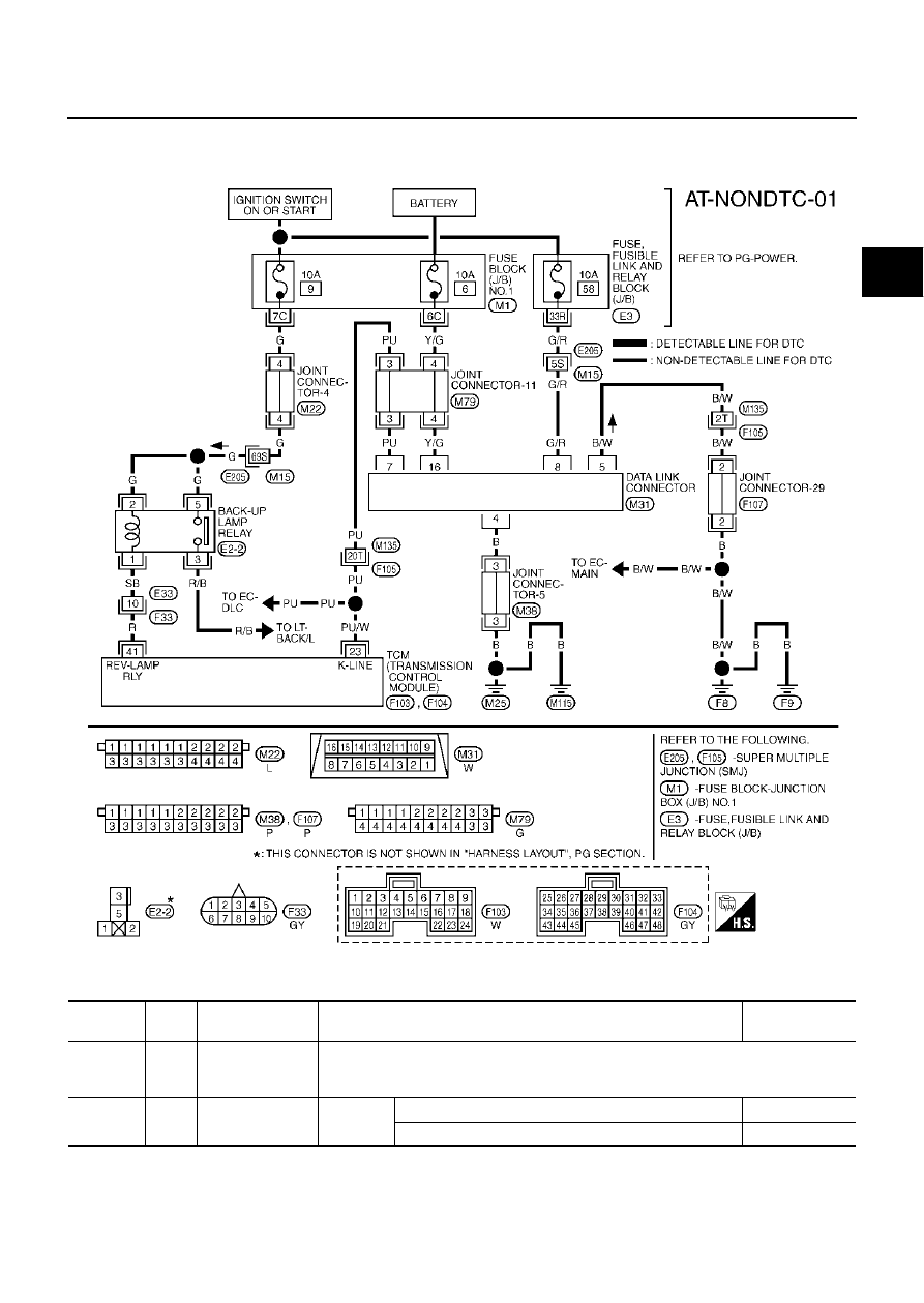
Wiring Diagram — AT — NONDTC

ECS00896

TCM terminals and data are reference value. Measured between each terminal and ground.

TCWM0103E

Terminal   

No.

Wire 

color

Item

Condition

Data (Approx.)

23

PU/W

K-line 
(CONSULT-II sig-
nal)

The terminal is connected to the Data link connector for CONSULT-II.

41

R

BACK-UP LAMP 
relay

IGN ON

Selector lever in “R” position.

0V

Selector lever in other position.

Battery voltage

AT-238

TROUBLE DIAGNOSIS FOR SYMPTOMS

A/T CHECK Indicator Lamp does not come on

ECS00897

SYMPTOM:

A/T CHECK indicator lamp does not come on for about 2 seconds when turning ignition switch to
“ON”.

DIAGNOSTIC PROCEDURE

1. 

CHECK CAN COMMUNICATION LINE

Execute the self-diagnosis. Is a malfunction in the CAN communication indicated in the results?

Yes or No

Yes

>> Check the CAN communication line. Refer to 

AT-99, "DTC U1000 CAN COMMUNICATION LINE"

.

No

>> GO TO 2.

2. 

CHECK TCM POWER SOURCE

1.

Turn ignition switch “ON”. (Do not start engine.)

2.

Check voltage between TCM connector terminals and ground.
Refer to 

AT-133, "Wiring Diagram — AT — POWER"

 .

3.

Turn ignition switch “OFF”.

4.

Check voltage between TCM connector terminals and ground.
Refer to 

AT-133, "Wiring Diagram — AT — POWER"

 .

OK or NG

OK

>> GO TO 4.

NG

>> GO TO 3.

3. 

DETECT MALFUNCTIONING ITEM

Check the following items:

Harness for short or open between battery and TCM connector terminal 9

Harness for short or open between ignition switch and TCM connector terminals 33 and 42

10A fuse [No. 32 or 35, located in the fuse block (J/B)]

Ignition switch, Refer to 

PG-2, "POWER SUPPLY ROUTING"

 .

OK or NG

OK

>> GO TO 4.

NG

>> Repair or replace damaged parts.

Item

Connector No.

Terminal No.

(Wire color)

Voltage

TCM

F103

9 (W/B) - Ground

Battery voltage

 F104

33 (G/R) - Ground

42 (G/R) - Ground

Item

Connector No.

Terminal No.

(Wire color)

Voltage

TCM

F103

9 (W/B) - Ground

Battery voltage

 F104

33 (G/R) - Ground

0V

42 (G/R) - Ground

SCIA1672E

TROUBLE DIAGNOSIS FOR SYMPTOMS

AT-239

D

E

F

G

H

I

J

K

L

M

A

B

AT

4. 

CHECK TCM GROUND CIRCUIT

1.

Turn ignition switch to “OFF”.

2.

Disconnect the TCM connector.

3.

Check continuity between terminals 5 (B), 14 (B), 24 (B), 46 (B)
and ground. Refer to 

AT-133, "Wiring Diagram — AT —

POWER"

 .

4.

If OK, check the harness for short-circuit to ground or the power
source.

OK or NG

OK

>> GO TO 5.

NG

>> Repair the short-circuit(s) in the harness or connector to

ground or the power source.

5. 

CHECK A/T CHECK INDICATOR LAMP CIRCUIT

1.

Turn ignition switch to “OFF”.

2.

Check the combination meter.
Refer to 

DI-7, "COMBINATION METERS"

 .

OK or NG

OK

>> GO TO 6.

NG

>> Replace the combination meter. Refer to 

DI-27, "Removal and Installation for Combination Meter"

.

6. 

CHECK SYMPTOM

Check again.

OK or NG

OK

>> INSPECTION END

NG

>> GO TO 7.

7. 

PERFORM TCM INSPECTION

1.

Perform TCM input/output signal inspection.

2.

If NG, recheck TCM pin terminals for damage or loose connection with harness connector.

OK or NG

OK

>> INSPECTION END

NG

>> Repair or replace damaged parts.

Engine Cannot Be Started In “P” or “N” Position

ECS00898

SYMPTOM:

Engine cannot be started with selector lever in “P” or “N” position.

Engine can be started with selector lever in “D”or “R” position.

DIAGNOSTIC PROCEDURE

1. 

CHECK PNP SWITCH CIRCUIT

Execute self-diagnosis.

Do the self-diagnostic results indicate PNP switch?

Yes

>> Check the malfunctioning system. Refer to 

AT-105, "DTC P0705 PARK/NEUTRAL POSITION

SWITCH"

 .

No

>> GO TO 2.

SCIA1161E

AT-240

TROUBLE DIAGNOSIS FOR SYMPTOMS

2. 

CHECK CONTROL LINKAGE

Check the control linkage.

Refer to 

AT-282, "Checking of A/T Position"

 .

OK or NG

OK

>> GO TO 3.

NG

>> Adjust control linkage. Refer to 

AT-282, "Adjustment of

A/T Position"

 .

3. 

CHECK STARTING SYSTEM

Check starting system. Refer to 

SC-22, "STARTING SYSTEM"

 .

OK or NG

OK

>> INSPECTION END

NG

>> Repair or replace damaged parts.

In “P” Position, Vehicle Moves When Pushed

ECS00899

SYMPTOM:

Even though the selector lever is set in the “P” position, the parking mechanism is not actuated,
allowing the vehicle to be moved when it is pushed.

DIAGNOSTIC PROCEDURE

1. 

CHECK PNP SWITCH CIRCUIT

Execute self-diagnosis.
Do the self-diagnostic results indicate PNP switch?

Yes

>> Check the malfunctioning system. Refer to 

AT-105, "DTC P0705 PARK/NEUTRAL POSITION

SWITCH"

 .

No

>> GO TO 2.

2. 

CHECK CONTROL LINKAGE

Check the control linkage.

Refer to 

AT-282, "Checking of A/T Position"

 .

OK or NG

OK

>> GO TO 3.

NG

>> Adjust control linkage. Refer to 

AT-282, "Adjustment of

A/T Position"

 .

3. 

CHECK PARKING COMPONENTS

Check parking components. Refer to 

AT-299, "Components"

 .

OK or NG

OK

>> INSPECTION END

NG

>> Repair or replace damaged parts.

SCIA1612E

SCIA1612E


Content   ..  86  87  88  89   ..