Infiniti F50. Manual - part 16
TROUBLE DIAGNOSIS — GENERAL DESCRIPTION
ACS-57
[ICC]
C
D
E
F
G
H
I
J
L
M
A
B
ACS
TROUBLE DIAGNOSIS — GENERAL DESCRIPTION
PFP:00004
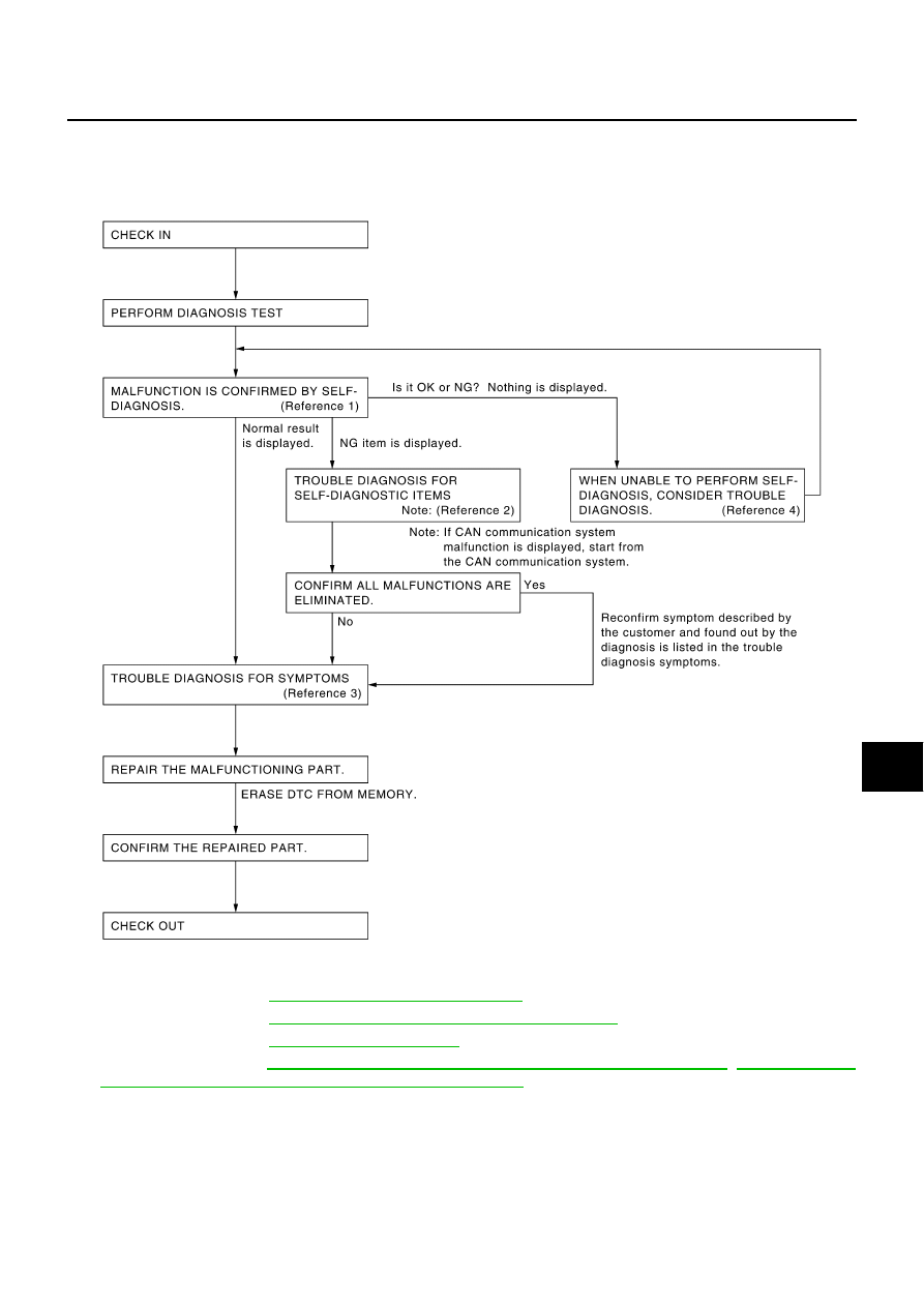
Work Flow
EKS003RG
●
Reference 1··· Refer to
ACS-63, "Self-Diagnostic Function"
●
Reference 2··· Refer to
ACS-68, "Diagnostic Trouble Code (DTC) Chart"
.
●
Reference 3··· Refer to
.
●
Reference 4···Refer to
ACS-65, "SELF-DIAGNOSIS BY CONSULT-II WILL NOT RUN"
DIAGNOSIS BY ICC SYSTEM DISPLAY WILL NOT RUN."
SKIA1227E