Index Infiniti Infiniti F50 - service repair manual 2006 year
Search
Content .. 13 14 15 16 ..
Infiniti F50. Manual - part 15
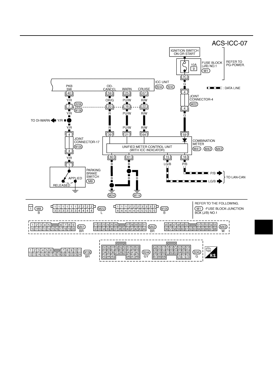
WIRING DIAGRAM
ACS-53
[ICC]
C
D
E
F
G
H
I
J
L
M
A
B
ACS
TKWM0449E