Infiniti I30 (A33). Manual - part 424
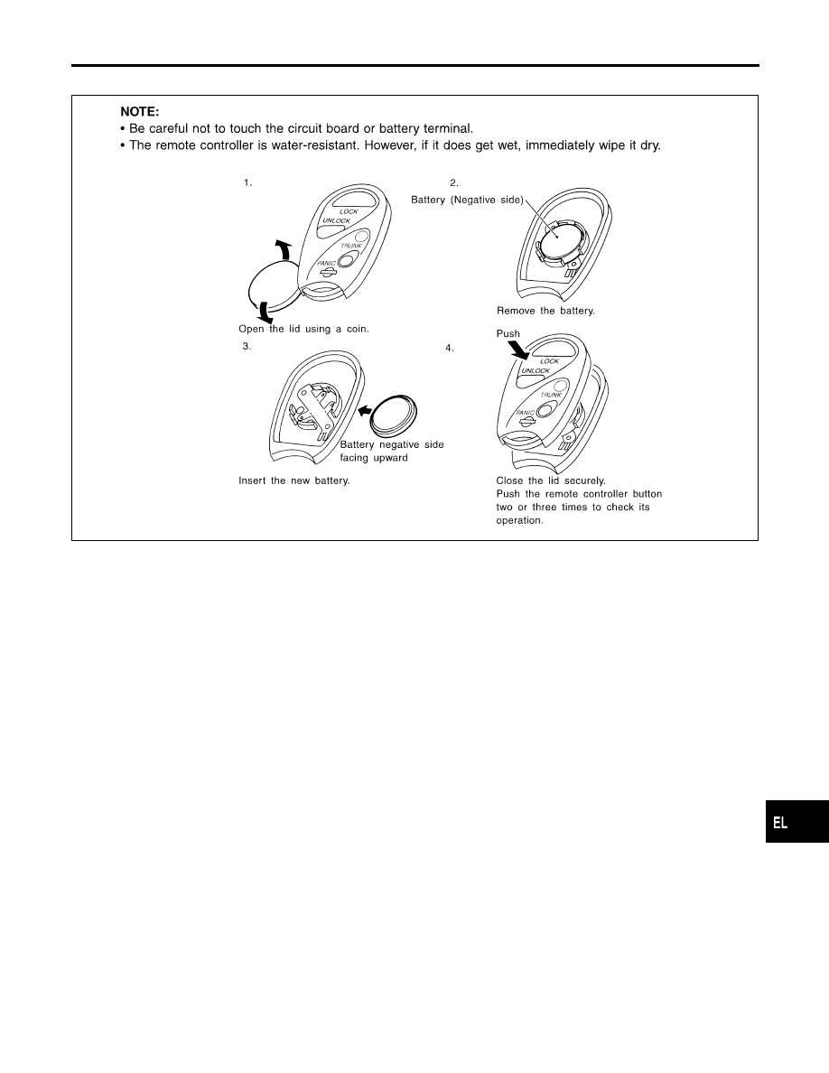
Remote Controller Battery Replacement
NHEL0118
SEL366W
GI
MA
EM
LC
EC
FE
AT
AX
SU
BR
ST
RS
BT
HA
SC
IDX
MULTI-REMOTE CONTROL SYSTEM
Remote Controller Battery Replacement
EL-365
|
|
|
Remote Controller Battery Replacement NHEL0118 SEL366W GI MA EM LC EC FE AT AX SU BR ST RS BT HA SC IDX MULTI-REMOTE CONTROL SYSTEM Remote Controller Battery Replacement EL-365 |