Infiniti I30 (A33). Manual - part 417
Component Parts and Harness Connector
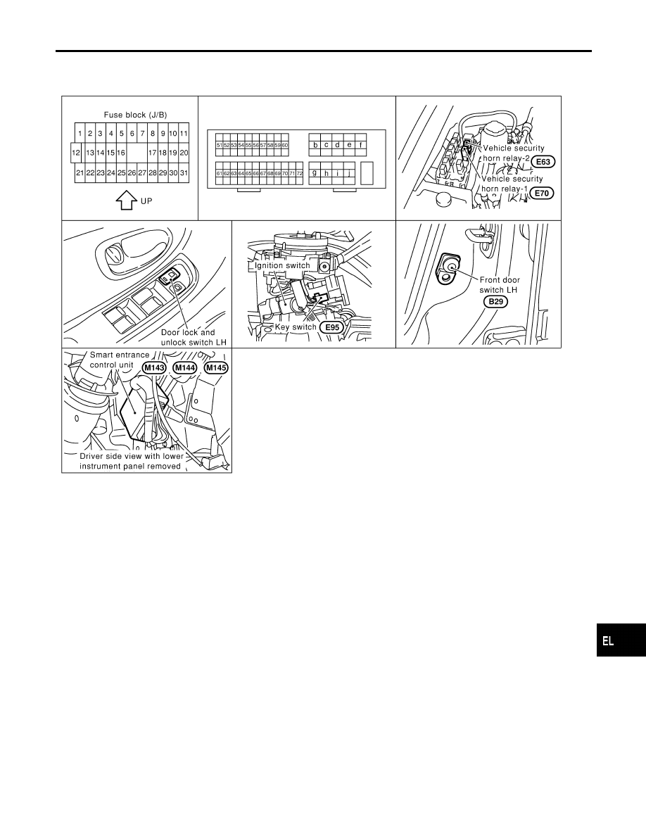
Location
NHEL0111
SEL054Y
System Description
NHEL0194
INPUTS
NHEL0194S01
Power is supplied at all times
I
to smart entrance control unit terminal 49 and
I
to key switch terminal 2
I
through 10A fuse [No. 13, located in the fuse block (J/B)].
When the key switch is ON (ignition key is inserted in key cylinder), power is supplied
I
through key switch terminal 1
I
to smart entrance control unit terminal 25.
When the front door switch LH is ON (door is OPEN), ground is supplied
I
to smart entrance control unit terminal 1
I
through front door switch LH terminal 2
I
to front door switch LH terminal 3
I
through body grounds B7 and B12 (without rear sunshade) or B46 (with rear sunshade).
When the front door switch RH is ON (door is OPEN), ground is supplied
I
to smart entrance control unit terminal 2
I
through front door switch RH terminal 2, and
I
to front door switch RH terminal 3
I
through body grounds B127 and B106.
When the rear door switches are ON (door is OPEN), ground is supplied
GI
MA
EM
LC
EC
FE
AT
AX
SU
BR
ST
RS
BT
HA
SC
IDX
MULTI-REMOTE CONTROL SYSTEM
Component Parts and Harness Connector Location
EL-337