Infiniti I30 (A33). Manual - part 116
SBR650E
GI
MA
EM
LC
EC
FE
AT
AX
SU
ST
RS
BT
HA
SC
EL
IDX
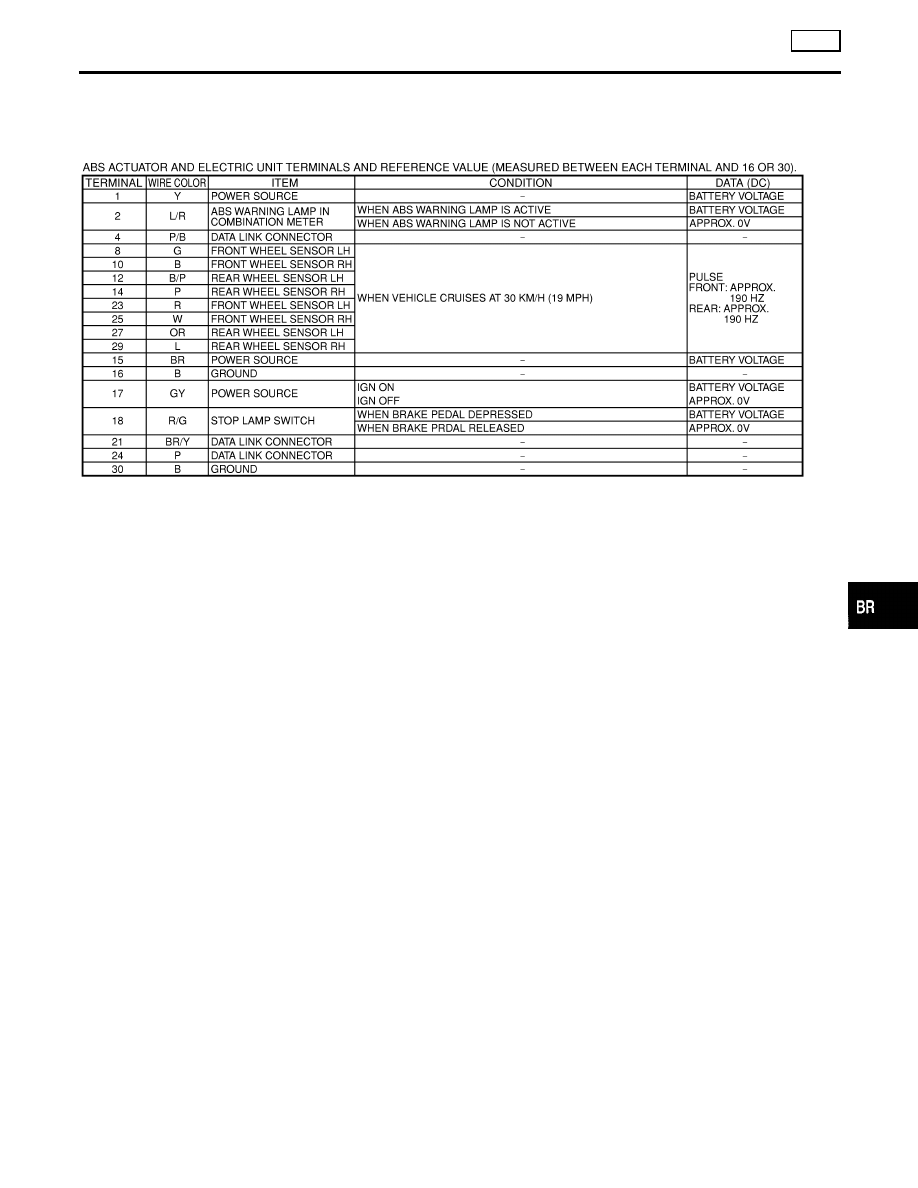
DESCRIPTION
ABS
Wiring Diagram — ABS — (Cont’d)
BR-47
|
|
|
SBR650E GI MA EM LC EC FE AT AX SU ST RS BT HA SC EL IDX DESCRIPTION ABS Wiring Diagram — ABS — (Cont’d) BR-47 |