Infiniti G37 Coupe. Manual - part 971


  Index      Infiniti     Infiniti G37 Coupe - service repair manual 2008 year


Search            


Content   ..  969  970  971  972   ..


Infiniti G37 Coupe. Manual - part 971


PCS

B260A IGNITION RELAY

PCS-53

< COMPONENT DIAGNOSIS >

[POWER DISTRIBUTION SYSTEM]

C

D

E

F

G

H

I

J

K

L

B

A

O

P

N

Is the inspection result normal?

YES

>> GO TO 4.

NO

>> GO TO 3.

3.

CHECK IGNITION RELAY (IPDM E/R) CIRCUIT

1.

Disconnect IPDM E/R harness connector E5.

2.

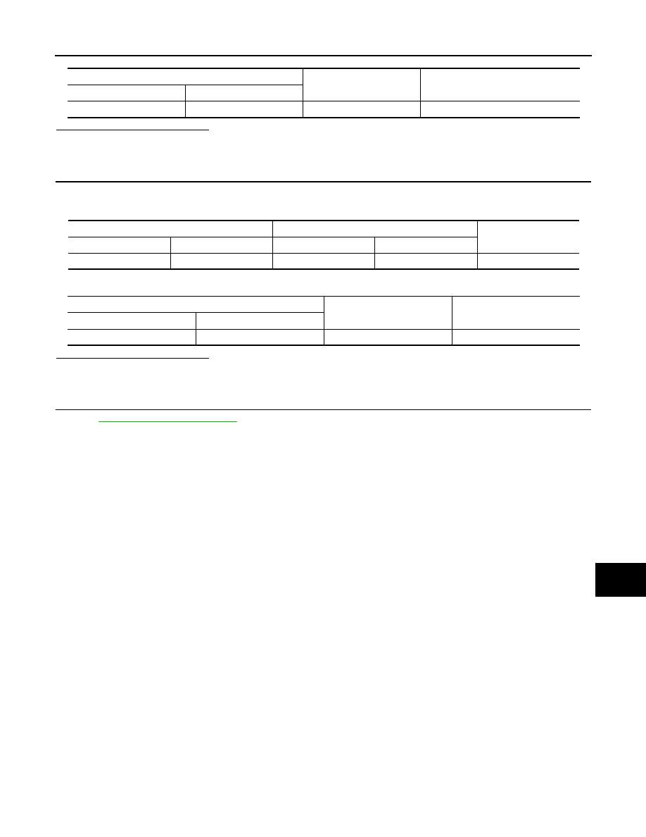
Check continuity between IPDM E/R harness connector and BCM harness connector.

3.

Check continuity between IPDM E/R harness connector and ground.

Is the inspection result normal?

YES

>> GO TO 4.

NO

>> Repair harness or connector.

4.

CHECK INTERMITTENT INCIDENT

Refer to 

GI-38, "Intermittent Incident"

.

>> INSPECTION END

BCM

Ground

Voltage [V]

Connector

Terminal

M121

47

Ground

Battery voltage

IPDM E/R

BCM

Continuity

Connector

Terminal

Connector

Terminal

E5

27

M121

47

Existed

IPDM E/R

Ground

Continuity

Connector

Terminal

E5

27

Ground

Not existed

PCS-54

< COMPONENT DIAGNOSIS >

[POWER DISTRIBUTION SYSTEM]

B2611 ACC RELAY

B2611 ACC RELAY

Description

INFOID:0000000001675273

BCM turns ON the ACC relay to supply ACC power to each ECU when the power supply position changes to
ACC.
BCM check ACC relay ON request for consistency with the actual ACC relay operation status.

DTC Logic

INFOID:0000000001675274

DTC DETECTION LOGIC

NOTE:
• If DTC B2611 is displayed with DTC U1000, first perform the trouble diagnosis for DTC U1000. Refer to

PCS-48, "DTC Logic"

.

• If DTC B2611 is displayed with DTC U1010, first perform the trouble diagnosis for DTC U1010. Refer to

PCS-49, "DTC Logic"

.

*: Electronic goods: Personal computer, CD player...

DTC CONFIRMATION PROCEDURE

1.

PERFORM DTC CONFIRMATION PROCEDURE–1

1.

Turn the power supply position to ACC under the following conditions, and wait for at least 2 seconds.

A/T models

-

A/T selector lever is in the P or N position

-

Do not depress brake pedal

M/T models

-

Do not depress clutch pedal

2.

Check “Self diagnostic result” with CONSULT-III.

Is DTC detected?

YES

>> Go to 

PCS-55, "Diagnosis Procedure"

.

NO

>> GO TO 2.

2.

PERFORM DTC CONFIRMATION PROCEDURE–2

1.

Turn the power supply position ACC to OFF under the following conditions, and wait for at least 2 sec-
onds.

A/T models

-

A/T selector lever is in the P or N position

-

Do not depress brake pedal

M/T models

-

Do not depress clutch pedal

2.

Check “Self diagnostic result” with CONSULT-III.

Is DTC detected?

YES

>> Go to 

PCS-55, "Diagnosis Procedure"

.

NO

>> GO TO 3.

3.

CHECK CIGARETTE LIGHTER SOCKET CONDITION

Check if the customer uses to connect some electronic goods* to the Cigarette lighter socket.
*: Electronic goods: Personal computer, CD player...
Has electronic good been connected to Cigarette lighter socket?

DTC No.

Trouble diagnosis 

name

DTC detecting condition

Possible cause

B2611

ACC RELAY

BCM detects a difference of signal for 2 seconds or 
more between the following information.
• ACC relay ON/OFF operation 
• ACC relay feedback.

• Harness or connectors

(ACC relay feed back circuit is 
open or shorted)

• Some electronic goods* connect to 

the cigarette lighter socket

PCS

B2611 ACC RELAY

PCS-55

< COMPONENT DIAGNOSIS >

[POWER DISTRIBUTION SYSTEM]

C

D

E

F

G

H

I

J

K

L

B

A

O

P

N

YES

>> DTC detection is possible.

NO

>> INSPECTION END

Diagnosis Procedure

INFOID:0000000001675275

1.

INSPECTION START

Confirm that the electronic good* connect to the cigarette lighter socket.
*: Electronic good: Personal computer, CD player...
Does electronic good connect to the cigarette lighter socket?

YES

>> Disconnect the electronic good, and perform once again the DTC confirmation procedure. Refer

to 

PCS-54, "DTC Logic"

.

NO

>> GO TO 2.

2.

CHECK ACCESSORY RELAY FEED BACK INPUT SIGNAL

1.

Turn ignition switch OFF.

2.

Disconnect BCM harness connector M123.

3.

Check voltage between BCM harness connector and ground under the following conditions.

Is the inspection result normal?

YES

>> GO TO 6.

NO

>> GO TO 3.

3.

CHECK ACCESSORY RELAY POWER SUPPLY CIRCUIT

1.

Turn ignition switch OFF.

2.

Disconnect accessory relay.

3.

Check voltage between accessory relay harness connector and ground.

Is the inspection result normal?

YES

>> GO TO 4.

NO

>> Check harness open or short between accessory relay and battery.

4.

CHECK FUSE

Check 10A fuse [No. 19, located fuse block (J/B)].
Is the inspection result normal?

YES

>> GO TO 5.

NO

>> Replace fuse.

5.

CHECK ACCESSORY RELAY FEEDBACK CIRCUIT

1.

Check continuity between accessory relay harness connector and BCM harness connector.

2.

Check continuity between accessory relay harness connector and ground.

BCM

Ground

Condition

Voltage (V)

Connector

Terminal

M123

122

Ground

Ignition switch

OFF

0

ACC

Battery voltage

Accessory relay

Ground

Voltage (V)

Terminal

5

Ground

Battery voltage

Accessory relay

BCM

Continuity

Terminal

Connector

Terminal

3

M123

122

Existed

PCS-56

< COMPONENT DIAGNOSIS >

[POWER DISTRIBUTION SYSTEM]

B2611 ACC RELAY

Is the inspection result normal?

YES

>> GO TO 6.

NO

>> Repair harness or connector.

6.

CHECK INTERMITTENT

Refer to 

GI-38, "Intermittent Incident"

.

>> INSPECTION END

Accessory relay

Ground

Continuity

Terminal

3

Ground

Not existed


Content   ..  969  970  971  972   ..