Infiniti G37 Coupe. Manual - part 927


  Index      Infiniti     Infiniti G37 Coupe - service repair manual 2008 year


Search            


Content   ..  925  926  927  928   ..


Infiniti G37 Coupe. Manual - part 927


MWI-54

< COMPONENT DIAGNOSIS >

FUEL LEVEL SENSOR SIGNAL CIRCUIT

FUEL LEVEL SENSOR SIGNAL CIRCUIT

Description

INFOID:0000000001606674

The fuel level sensor unit and fuel pump (main) and the fuel level sensor unit (sub) detect the fuel level in the
fuel tank and transmit the fuel gauge signal to the unified meter and A/C amp.

Component Function Check

INFOID:0000000001606675

1.

CHECK UNIFIED METER AND A/C AMP. OUTPUT SIGNAL

1.

Connect the CONSULT-III.

2.

Select the “Data Monitor” for the “METER/M&A” and compare the “FUEL METER” monitor value with the
fuel gauge reading on the combination meter.

Does monitor value match fuel gauge reading?

YES

>> INSPECTION END

NO

>> Replace combination meter.

Diagnosis Procedure

INFOID:0000000001606676

1.

CHECK UNIFIED METER AND A/C AMP. INPUT SIGNAL

1.

Turn ignition switch ON.

2.

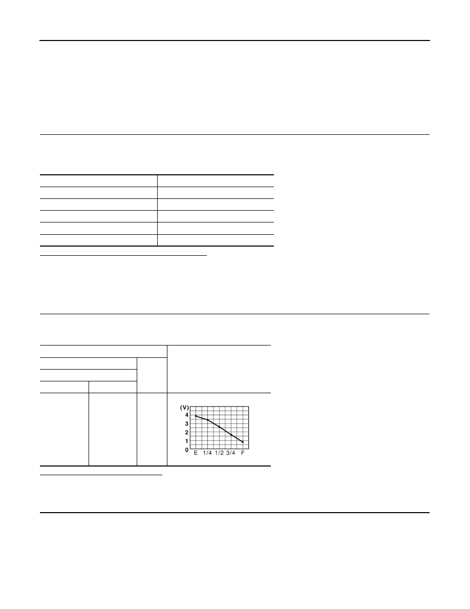
Check voltage between unified meter and A/C amp. harness connector terminal and ground.

Does it match fuel gauge reading?

YES

>> GO TO 2.

NO

>> Replace the unified meter and A/C amp.

2.

CHECK FUEL LEVEL SENSOR (SUB) CIRCUIT

1.

Turn ignition switch OFF.

2.

Disconnect unified meter and A/C amp. connector and fuel level sensor unit (sub) connector.

3.

Check continuity between unified meter and A/C amp. harness connector terminal and fuel level sensor
unit (sub) harness connector terminal.

Fuel gauge pointer

Reference value of data monitor [lit.]

Full

Approx. 68.8

Three quarters

Approx. 60

Half

Approx. 39.2

A quarter

Approx. 20.8

Empty

Approx. 5.6

Terminal

Voltage

(Approx.)

(+)

(–)

Unified meter and A/C amp.

Connector

Terminal

M67

42

Ground

JSNIA0013GB

MWI

FUEL LEVEL SENSOR SIGNAL CIRCUIT

MWI-55

< COMPONENT DIAGNOSIS >

C

D

E

F

G

H

I

J

K

L

M

B

A

O

P

4.

Check continuity between unified meter and A/C amp. harness connector terminal and ground.

Is the inspection result normal?

OK

>> GO TO 3.

NG

>> Repair harness or connector.

3.

CHECK FUEL LEVEL SENSOR (MAIN-SUB) CIRCUIT

1.

Disconnect fuel level sensor unit and fuel pump (main) connector.

2.

Check continuity between fuel level sensor unit (sub) harness connector terminal and fuel level sensor
unit and fuel pump (main) harness connector terminal.

3.

Check continuity between fuel level sensor unit (sub) harness connector terminal and ground.

Is the inspection result normal?

OK

>> GO TO 4.

NG

>> Repair harness or connector.

4.

CHECK FUEL LEVEL SENSOR (MAIN) CIRCUIT

Check continuity between fuel level sensor unit and fuel pump (main) harness connector terminal and unified
meter and A/C amp. harness connector terminal.

Is the inspection result normal?

OK

>> GO TO 5.

NG

>> Repair harness or connector.

5.

CHECK INSTALLATION CONDITION

Check fuel level sensor unit installation, and check whether the float arm interferes or binds with any of the
internal components in the fuel tank.

Is the inspection result normal?

YES

>> INSPECTION END

NO

>> Install the fuel level sensor unit properly.

Component Inspection

INFOID:0000000001606677

1.

REMOVE FUEL LEVEL SENSOR UNIT

Remove the fuel level sensor unit. Refer to 

FL-5, "Removal and Installation"

.

Unified meter and A/C amp.

Fuel level sensor unit (sub)

Continuity

Connector

Terminal

Connector

Terminal

M67

42

B21

1

Existed

Unified meter and A/C amp.

Ground

Continuity

Connector

Terminal

M67

42

Not existed

Fuel level sensor unit (sub)

Fuel level sensor unit (main)

Continuity

Connector

Terminal

Connector

Terminal

B21

2

B22

2

Existed

Fuel level sensor unit (sub)

Ground

Continuity

Connector

Terminal

B21

2

Not existed

Fuel level sensor unit (main)

Unified meter and A/C amp.

Continuity

Connector

Terminal

Connector

Terminal

B22

5

M67

58

Existed

MWI-56

< COMPONENT DIAGNOSIS >

FUEL LEVEL SENSOR SIGNAL CIRCUIT

>> GO TO 2.

2.

CHECK FUEL LEVEL SENSOR UNIT AND FUEL PUMP (MAIN)

Check the resistance between fuel level sensor unit and fuel pump
(main).

Standard float position

Is the inspection result OK?

YES

>> GO TO 3.

NO

>> Replace fuel level sensor unit and fuel pump (main).

3.

CHECK FUEL LEVEL SENSOR UNIT (SUB)

Inspect the resistance of fuel level sensor unit (sub).

Standard float position

Is the inspection result OK?

YES

>> INSPECTION END

NO

>> Replace fuel level sensor unit (sub).

Terminal

Float position

Resistance value (

)

2

5

Full (A)

Approx. 3

Empty (B)

Approx. 80

JSNIA0110ZZ

Float position [mm (in)]

Full

Approx. 210 (8.27)

Empty

Approx. 30 (1.18)

Terminal

Float position

Resistance value (

)

1

2

Full (A)

Approx. 3

Empty (B)

Approx. 43

JSNIA0111ZZ

Float position [mm (in)]

Full

Approx. 9 (0.35)

Empty

Approx. 179 (7.05)

MWI

METER CONTROL SWITCH SIGNAL CIRCUIT

MWI-57

< COMPONENT DIAGNOSIS >

C

D

E

F

G

H

I

J

K

L

M

B

A

O

P

METER CONTROL SWITCH SIGNAL CIRCUIT

Description

INFOID:0000000001606678

Transmits the following signals to the combination meter.

Diagnosis Procedure

INFOID:0000000001606679

1.

CHECK METER CONTROL SWITCH INPUT SIGNAL

1.

Turn the ignition switch ON.

2.

Measure voltage between the following terminals of the combination meter.

Is the inspection result normal?

YES

>> INSPECTION END

NO

>> GO TO 2.

2.

CHECK METER CONTROL SWITCH SIGNAL CIRCUIT

1.

Turn the ignition switch OFF.

2.

Disconnect the combination meter and meter control switch connectors.

3.

Check continuity between combination meter harness connector terminal and meter control switch har-
ness connector terminal.

4.

Check continuity between combination meter harness connector terminal and ground.

 (Illumination control) switch signal (+)

 (Illumination control) switch signal (–)

• Trip A/B reset switch signal

 (select) switch signal

 (enter) switch is pressed

Terminal 

No.

Condition

Voltage

36 - 16

When 

 (select) switch is pressed

0 V

Other than the above

5 V

37 - 16

When 

 (enter) switch is pressed

0 V

Other than the above

5 V

38 - 16

When trip A/B reset switch is pressed

0 V

Other than the above

5 V

39 - 16

When 

 (illumination control) switch is 

pressed

0 V

Other than the above

5 V

40 - 16

When 

 (illumination control) switch is 

pressed

0 V

Other than the above

5 V

Combination meter

Meter control switch

Continuity

Connector

Terminals

Connector

Terminals

M53

16

M54

7

Existed

36

2

37

1

39

10

40

9

38

5


Content   ..  925  926  927  928   ..