Infiniti G37 Coupe. Manual - part 815
INL-94
< ECU DIAGNOSIS >
COMBINATION METER
DTC Index
INFOID:0000000001830730
.
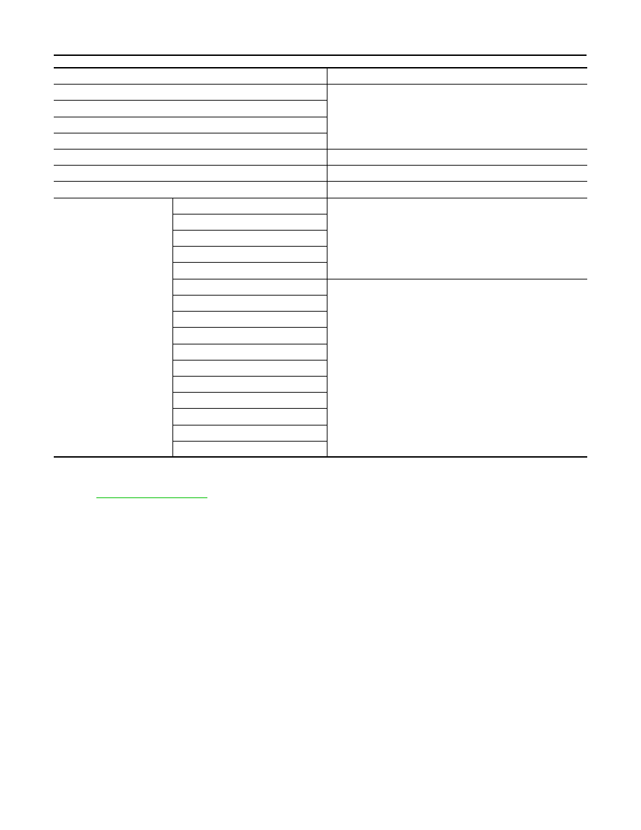
Function
Specifications
Speedometer
Reset to zero by suspending communication.
Tachometer
Fuel gauge
Water temperature gauge
Illumination control
When suspending communication, change to nighttime mode.
Information display
The display turns off by suspending communication.
Buzzer
The buzzer turns off by suspending communication.
Warning lamp/indicator
lamp
ABS warning lamp
The lamp turns on by suspending communication.
VDC OFF indicator lamp
SLIP indicator lamp
Brake warning lamp
CRUISE warning lamp
High beam indicator
The lamp turns off by suspending communication.
Turn signal indicator lamp
Front fog indicator lamp
Oil pressure warning lamp
Malfunction indicator lamp
A/T CHECK warning lamp
Low tire pressure warning lamp
Key warning lamp
AFS OFF indicator lamp
4WAS warning lamp
Master warning lamp