Infiniti G37 Coupe. Manual - part 573
P2A00, P2A03 A/F SENSOR 1
EC-473
< COMPONENT DIAGNOSIS >
[VQ37VHR]
C
D
E
F
G
H
I
J
K
L
M
A
EC
N
P
O
Is the inspection result normal?
YES
>> GO TO 8.
NO
>> GO TO 7.
7.
DETECT MALFUNCTIONING PART
Check the following.
• Harness connectors E3, F1
• IPDM E/R harness connector E7
• 15A fuse (No. 46)
• Harness for open or short between A/F sensor 1 and fuse
>> Repair or replace harness or connectors.
8.
CHECK A/F SENSOR 1 INPUT SIGNAL CIRCUIT FOR OPEN AND SHORT
1.
Turn ignition switch OFF.
2.
Disconnect ECM harness connector.
3.
Check the continuity between A/F sensor 1 harness connector and ECM harness connector.
4.
Check the continuity between A/F sensor 1 harness connector or ECM harness connector and ground.
5.
Also check harness for short to power.
Is the inspection result normal?
YES
>> GO TO 9.
NO
>> Repair open circuit or short to ground or short to power in harness or connectors.
9.
CHECK A/F SENSOR 1 HEATER
EC-157, "Component Inspection"
Is the inspection result normal?
YES
>> GO TO 10.
NO
>> GO TO 11.
10.
CHECK INTERMITTENT INCIDENT
Perform
GI-38, "Intermittent Incident"
.
Is the inspection result normal?
YES
>> GO TO 11.
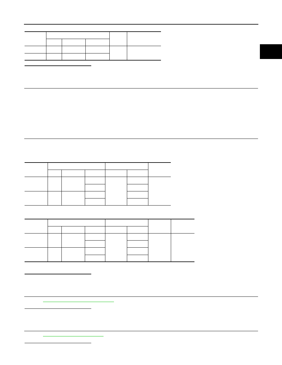
DTC
A/F sensor 1
Ground
Voltage
Bank
Connector
Terminal
P2A00
1
F3
4
Ground
Battery voltage
P2A03
2
F20
4
DTC
A/F sensor 1
ECM
Continuity
Bank
Connector
Terminal
Connector
Terminal
P2A00
1
F3
1
F102
57
Existed
2
61
P2A03
2
F20
1
65
2
66
DTC
A/F sensor 1
ECM
Ground
Continuity
Bank
Connector
Terminal
Connector
Terminal
P2A00
1
F3
1
F102
57
Ground
Not existed
2
61
P2A03
2
F20
1
65
2
66