Infiniti G37 Coupe. Manual - part 572


  Index      Infiniti     Infiniti G37 Coupe - service repair manual 2008 year


Search            


Content   ..  570  571  572  573   ..


Infiniti G37 Coupe. Manual - part 572


P2138 APP SENSOR

EC-469

< COMPONENT DIAGNOSIS >

[VQ37VHR]

C

D

E

F

G

H

I

J

K

L

M

A

EC

N

P

O

1.

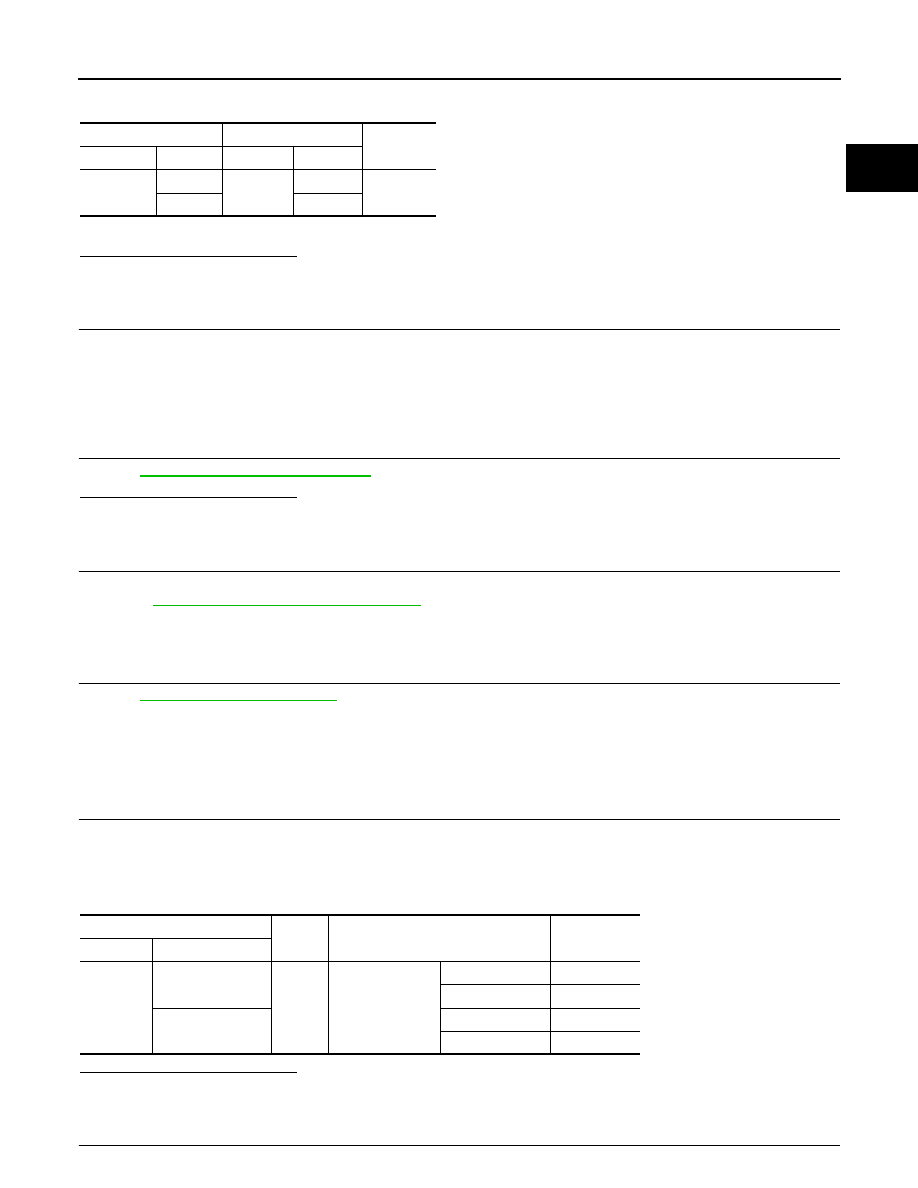
Check the continuity between APP sensor harness connector and ECM harness connector.

2.

Also check harness for short to ground and short to power.

Is the inspection result normal?

YES

>> GO TO 13.

NO

>> GO TO 12.

12.

DETECT MALFUNCTIONING PART

Check the following.
• Harness connectors M6, E106
• Harness for open or short between ECM and accelerator pedal position sensor

>> Repair open circuit or short to ground or short to power in harness or connectors.

13.

CHECK APP SENSOR

Refer to 

EC-469, "Component Inspection"

.

Is the inspection result normal?

YES

>> GO TO 15.

NO

>> GO TO 14.

14.

REPLACE ACCELERATOR PEDAL ASSEMBLY

1.

Replace accelerator pedal assembly.

2.

Go to 

EC-470, "Special Repair Requirement"

.

>> INSPECTION END

15.

CHECK INTERMITTENT INCIDENT

Refer to 

GI-38, "Intermittent Incident"

.

>> INSPECTION END

Component Inspection

INFOID:0000000001911134

1.

CHECK ACCELERATOR PEDAL POSITION SENSOR

1.

Turn ignition switch OFF.

2.

Reconnect all harness connectors disconnected.

3.

Turn ignition switch ON.

4.

Check the voltage ECM harness connector and ground.

Is the inspection result normal?

YES

>> INSPECTION END

NO

>> GO TO 2.

2.

REPLACE ACCELERATOR PEDAL ASSEMBLY

APP sensor

ECM

Continuity

Connector

Terminal

Connector

Terminal

E112

3

M107

97

Existed

1

98

ECM

Ground

Condition

Voltage

Connector

Terminal

M107

97 (APP sensor 1)

Ground

Accelerator pedal

Fully released

0.45 - 1.00V

Fully depressed

4.4 - 4.8V

98 (APP sensor 2)

Fully released

0.22 - 0.50V

Fully depressed

2.1 - 2.5V

EC-470

< COMPONENT DIAGNOSIS >

[VQ37VHR]

P2138 APP SENSOR

1.

Replace accelerator pedal assembly.

2.

Go to 

EC-470, "Special Repair Requirement"

.

>> INSPECTION END

Special Repair Requirement

INFOID:0000000001911135

1.

PERFORM ACCELERATOR PEDAL RELEASED POSITION LEARNING

Refer to 

EC-18, "ACCELERATOR PEDAL RELEASED POSITION LEARNING : Special Repair Requirement"

.

>> GO TO 2.

2.

PERFORM THROTTLE VALVE CLOSED POSITION LEARNING

Refer to 

EC-18, "THROTTLE VALVE CLOSED POSITION LEARNING : Special Repair Requirement"

.

>> GO TO 3.

3.

PERFORM IDLE AIR VOLUME LEARNING

Refer to 

EC-19, "IDLE AIR VOLUME LEARNING : Special Repair Requirement"

.

>> END

P2A00, P2A03 A/F SENSOR 1

EC-471

< COMPONENT DIAGNOSIS >

[VQ37VHR]

C

D

E

F

G

H

I

J

K

L

M

A

EC

N

P

O

P2A00, P2A03 A/F SENSOR 1

Description

INFOID:0000000001911129

The air fuel ratio (A/F) sensor 1 is a planar one-cell limit current sen-
sor. The sensor element of the A/F sensor 1 is composed an elec-
trode layer, which transports ions. It has a heater in the element.
The sensor is capable of precise measurement   = 1, but also in the
lean and rich range. Together with its control electronics, the sensor
outputs a clear, continuous signal throughout a wide   range.
The exhaust gas components diffuse through the diffusion layer at
the sensor cell. An electrode layer is applied voltage, and this current
relative oxygen density in lean. Also this current relative hydrocar-
bon density in rich.

Therefore, the A/F sensor 1 is able to indicate air fuel ratio by this
electrode layer of current. In addition, a heater is integrated in the
sensor to ensure the required operating temperature of about 800

°

C

(1,472

°

F).

DTC Logic

INFOID:0000000001734295

DTC DETECTION LOGIC

To judge the malfunction, the A/F signal computed by ECM from the A/F sensor 1 signal is monitored not to be
shifted to LEAN side or RICH side.

DTC CONFIRMATION PROCEDURE

1.

PRECONDITIONING

If DTC Confirmation Procedure has been previously conducted, always perform the following before conduct-
ing the next test. 
1.

Turn ignition switch OFF and wait at least 10 seconds.

2.

Turn ignition switch ON.

3.

Turn ignition switch OFF and wait at least 10 seconds.

TESTING CONDITION:
Before performing the following procedure, confirm that battery voltage is more than 11V at idle.

>> GO TO 2.

2.

PERFORM DTC CONFIRMATION PROCEDURE

1.

Clear the mixture ratio self-learning value. Refer to 

EC-22, "MIXTURE RATIO SELF-LEARNING VALUE

CLEAR : Special Repair Requirement"

.

2.

Turn ignition switch OFF and wait at least 10 seconds.

JMBIA0112GB

PBIB3354E

DTC No.

Trouble diagnosis name

DTC detecting condition

Possible Cause

P2A00

Air fuel ratio (A/F) sensor 1 
(bank 1) circuit range/per-
formance

• The output voltage computed by ECM from the 

A/F sensor 1 signal is shifted to the lean side for 
a specified period.

• The A/F signal computed by ECM from the A/F 

sensor 1 signal is shifted to the rich side for a 
specified period.

• A/F sensor 1
• A/F sensor 1 heater
• Fuel pressure
• Fuel injector
• Intake air leaks

P2A03

Air fuel ratio (A/F) sensor 1 
(bank 2) circuit range/per-
formance

EC-472

< COMPONENT DIAGNOSIS >

[VQ37VHR]

P2A00, P2A03 A/F SENSOR 1

3.

Turn ignition switch ON.

4.

Turn ignition switch OFF and wait at least 10 seconds.

5.

Start engine and keep the engine speed between 3,500 and 4,000 rpm for 1 minute under no load.

6.

Let engine idle for 1 minute.

7.

Keep engine speed between 2,500 and 3,000 rpm for 20 minutes.

8.

Check 1st trip DTC.

Is 1st trip DTC detected?

YES

>> Go to 

EC-472, "Diagnosis Procedure"

.

NO

>> INSPECTION END

Diagnosis Procedure

INFOID:0000000001734296

1.

CHECK GROUND CONNECTION

1.

Turn ignition switch OFF.

2.

Check ground connection M95. Refer to Ground Inspection in 

GI-41, "Circuit Inspection"

.

Is the inspection result normal?

YES

>> GO TO 2.

NO

>> Repair or replace ground connection.

2.

RETIGHTEN A/F SENSOR 1

1.

Loosen and retighten the A/F sensor 1. Refer to 

EM-33, "Removal and Installation"

.

>> GO TO 3.

3.

CHECK FOR INTAKE AIR LEAK

1.

Start engine and run it at idle.

2.

Listen for an intake air leak after the mass air flow sensor.

Is intake air leak detected?

YES

>> Repair or replace.

NO

>> GO TO 4.

4.

CLEAR THE MIXTURE RATIO SELF-LEARNING VALUE

1.

Clear the mixture ratio self-learning value. Refer to 

EC-22, "MIXTURE RATIO SELF-LEARNING VALUE

CLEAR : Special Repair Requirement"

.

2.

Run engine for at least 10 minutes at idle speed.

Is the 1st trip DTC P0171, P0172, P0174 or P0175 detected? Is it difficult to start engine?

YES

>> Perform trouble diagnosis for DTC P0171, P0174 or P0172, P0175. Refer to 

EC-233, "Diagnosis

Procedure"

 or 

EC-237, "Diagnosis Procedure"

.

NO

>> GO TO 5.

5.

CHECK HARNESS CONNECTOR

1.

Turn ignition switch OFF.

2.

Disconnect A/F sensor 1 harness connector.

3.

Check harness connector for water. 

Is the inspection result normal?

YES

>> GO TO 6.

NO

>> Repair or replace harness connector.

6.

CHECK A/F SENSOR 1 POWER SUPPLY CIRCUIT

1.

Turn ignition switch ON.

2.

Check the voltage between A/F sensor 1 harness connector and ground.

Water should not exit.


Content   ..  570  571  572  573   ..