Infiniti G37 Coupe. Manual - part 444


  Index      Infiniti     Infiniti G37 Coupe - service repair manual 2008 year


Search            


Content   ..  442  443  444  445   ..


Infiniti G37 Coupe. Manual - part 444


DLN-90

< REMOVAL AND INSTALLATION >

[REAR FINAL DRIVE: R200V]

REAR FINAL DRIVE ASSEMBLY

1.

Remove center muffler with a power tool. Refer to 

EX-5, "Exploded View"

.

2.

Remove rear stabilizer bar with a power tool. Refer to 

RSU-21, "Exploded View"

.

3.

Remove propeller shaft from the final drive. Refer to 

DLN-14, "Exploded View"

.

4.

Remove drive shaft from final drive with a power tool. Then sus-
pend it by wire, etc. Refer to 

RAX-10, "Exploded View"

.

5.

Remove breather hose from the final drive.

6.

Remove rear wheel sensor. Refer to 

BRC-100, "Exploded

View"

.

7.

Set a suitable jack to rear final drive assembly.

CAUTION:

Never place a jack on the rear cover (aluminum case).

8.

Remove the mounting bolts and nuts connecting to the suspen-
sion member, and remove rear final drive assembly with a power
tool.

CAUTION:

Secure rear final drive assembly to a suitable jack while
removing it.

INSTALLATION

Note the following, and installation is in the reverse order of removal.
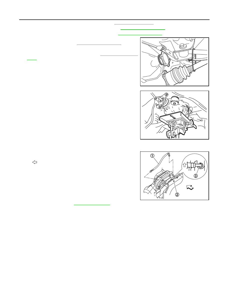
• When installing breather hoses (1), refer to the figure.

CAUTION:

Make sure there are no pinched or restricted areas on the
breather hose caused by bending or winding when installing
it.

- For installation, insert the vehicle side end to suspension member

(2). Install metal connector (3) side of this hose to rear cover by
inserting it with aiming painted marking to the front of vehicle.

• When oil leaks while removing final drive assembly, check oil level

after the installation. Refer to 

DLN-69, "Inspection"

.

SDIA1094E

JSDIA0026ZZ

: Vehicle front

PDIA0754E

DIFFERENTIAL ASSEMBLY

DLN-91

< DISASSEMBLY AND ASSEMBLY >

[REAR FINAL DRIVE: R200V]

C

E

F

G

H

I

J

K

L

M

A

B

DLN

N

O

P

DISASSEMBLY AND ASSEMBLY

DIFFERENTIAL ASSEMBLY

M/T

M/T : Exploded View

INFOID:0000000001714272

1.

Drive pinion lock nut

2.

Companion flange

3.

Front oil seal

4.

Pinion front bearing

5.

Gear carrier

6.

Side oil seal

7.

Side flange

8.

Collapsible spacer

9.

Pinion rear bearing

10. Pinion height adjusting washer

11.

Drive pinion

12. Side bearing adjusting washer

13. Side bearing

14. Drive gear

15. Differential case B

16. Side gear thrust washer

17. Circular clip

18. Side gear

19. Pinion mate shaft

20. Pinion mate thrust washer

21. Pinion mate gear

22. Viscous coupling

23. Differential case A

24. Bearing cap

25. Filler plug

26. Gasket

27. Rear cover

28. Drain plug

A.

Oil seal lip

B.

Screw hole

C.

After tightening the bolts to the spec-
ified torque, tighten the bolts addi-
tionally by turning the bolts 31 to 36 
degrees.

:

Apply gear oil.

:

Apply anti-corrosion oil.

:

Apply Genuine Silicone RTV or equivalent. Refer to 

GI-15, "Recommended Chemical Products and Sealants"

.

JSDIA0037GB

DLN-92

< DISASSEMBLY AND ASSEMBLY >

[REAR FINAL DRIVE: R200V]

DIFFERENTIAL ASSEMBLY

M/T : Disassembly

INFOID:0000000001714273

1.

Drain gear oil, if necessary.

2.

Remove side flange.

3.

Remove rear cover mounting bolts.

4.

Remove rear cover to insert the seal cutter (A) [SST:
KV10111100 (J-37228)] between gear carrier and rear cover.

CAUTION:

• Never damage the mating surface.
• Never insert flat-bladed screwdriver, this may damage the

mating surface.

5.

Using two 45 mm (1.77 in) spacers, mount carrier on the attach-
ment (A) [SST: KV38100800 (J-25604-01)].

6.

For proper reinstallation, paint matching marks on one side of
the bearing cap.

CAUTION:

• For matching marks, use paint. Never damage bearing

caps and gear carrier.

• Bearing caps are manufactured as integral molding. Use

the matching marks to them in their original positions.

7.

Remove bearing caps.

:

Apply Genuine High Strength Thread Locking Sealant or equivalent. Refer to 

GI-15, "Recommended Chemical Products 

and Sealants"

.

Refer to 

GI-4, "Components"

 for symbols not described on the above.

PDIA0756J

JSDIA0041ZZ

PDIA0069E

S-PD343

DIFFERENTIAL ASSEMBLY

DLN-93

< DISASSEMBLY AND ASSEMBLY >

[REAR FINAL DRIVE: R200V]

C

E

F

G

H

I

J

K

L

M

A

B

DLN

N

O

P

8.

Lift differential case assembly out with a suitable tool.

• Keep side bearing outer races together with inner race. Do not

mix them up.
Also, keep side bearing adjusting washers together with bear-
ings.

9.

Remove side bearing inner race.
To prevent damage to bearing, engage puller jaws in groove
(

).

CAUTION:

• To prevent damage to the side bearing and drive gear,

place copper plates between these parts and vise.

• It is not necessary to remove side bearing inner race

except when it is replaced.

10. For proper reinstallation, paint matching marks on one differen-

tial case assembly.

CAUTION:

For matching marks, use paint. Never damage differential
case and drive gear.

11. Remove drive gear mounting bolts.
12. Tap drive gear off differential case assembly with a soft hammer.

CAUTION:

Tap evenly all around to keep drive gear from bending.

PDIA0547E

SPD919

A: Puller [SST: ST33051001 (J-22888-20)]

B: Base [SST: ST33061000 (J-8107-2)]

JSDIA0044ZZ

PDIA0496E


Content   ..  442  443  444  445   ..