Infiniti G37 Coupe. Manual - part 443


  Index      Infiniti     Infiniti G37 Coupe - service repair manual 2008 year


Search            


Content   ..  441  442  443  444   ..


Infiniti G37 Coupe. Manual - part 443


DLN-86

< ON-VEHICLE REPAIR >

[REAR FINAL DRIVE: R200V]

SIDE OIL SEAL

A/T : Removal and Installation

INFOID:0000000001714267
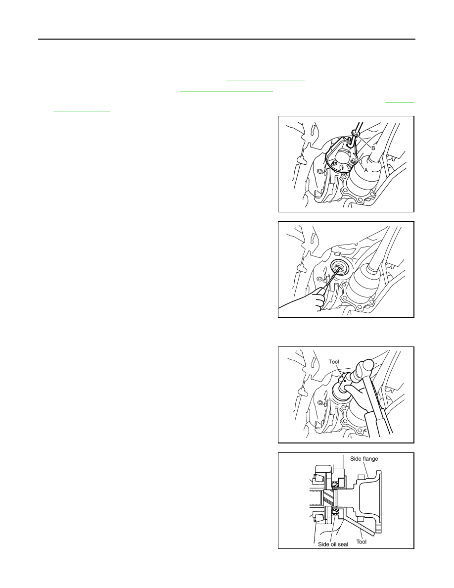
REMOVAL

1.

Remove center muffler with a power tool. Refer to 

EX-5, "Exploded View"

.

2.

Remove rear wheel sensor. Refer to 

BRC-100, "Exploded View"

.

3.

Remove drive shaft from final drive with a power tool. Then suspend it by wire, etc. Refer to 

RAX-10,

"Exploded View"

4.

Install attachment (A) [SST: KV40104100 (

)] to side

flange, and then pull out the side flange with the sliding hammer
(B) [SST: ST36230000 (J-25840-A)].
NOTE:
Circular clip installation position: Final drive side

5.

Remove side oil seal, using a flat-bladed screwdriver.

CAUTION:

Never damage gear carrier.

INSTALLATION

1.

Apply multi-purpose grease to side oil seal lips.

2.

Install side oil seal until it becomes flush with the case end,
using the drift [SST: KV38100200 (J-26233)].

CAUTION:

• Never reuse oil seal.
• When installing, never incline oil seal.

3.

Install side flange with the following procedure.

a.

Attach the protector [SST: KV38107900 (J-39352)] to side oil
seal.

b.

After the side flange is inserted and the serrated part of side
gear has engaged the serrated part of flange, remove the pro-
tector.

c.

Put a suitable drift on the center of side flange, then drive it until sound changes.

JSDIA0105ZZ

SDIA1584E

SDIA1585E

SDIA0822E

SIDE OIL SEAL

DLN-87

< ON-VEHICLE REPAIR >

[REAR FINAL DRIVE: R200V]

C

E

F

G

H

I

J

K

L

M

A

B

DLN

N

O

P

NOTE:
When installation is completed, driving sound of the side flange turns into a sound that seems to affect the
whole final drive.

d.

Confirm that the dimension of the side flange (1) installation
(Measurement A) in the figure comes into the following.

4.

Install drive shaft. Refer to 

RAX-10, "Exploded View"

.

5.

Install rear wheel sensor. Refer to 

BRC-100, "Exploded View"

.

6.

Install center muffler. Refer to 

EX-5, "Exploded View"

.

7.

When oil leaks while removing, check oil level after the installa-
tion. Refer to 

DLN-69, "Inspection"

.

Measurement “A”

: 326 – 328 mm (12.83 – 
12.91 in)

JSDIA0110ZZ

DLN-88

< REMOVAL AND INSTALLATION >

[REAR FINAL DRIVE: R200V]

REAR FINAL DRIVE ASSEMBLY

REMOVAL AND INSTALLATION

REAR FINAL DRIVE ASSEMBLY

M/T

M/T : Exploded View

INFOID:0000000001714268

M/T : Removal and Installation

INFOID:0000000001714269

REMOVAL

1.

Remove center muffler with a power tool. Refer to 

EX-5, "Exploded View"

.

2.

Remove rear stabilizer bar with a power tool. Refer to 

RSU-21, "Exploded View"

.

3.

Remove propeller shaft from the final drive. Refer to 

DLN-7, "Exploded View"

.

4.

Remove drive shaft from final drive with a power tool. Then sus-
pend it by wire, etc. Refer to 

RAX-10, "Exploded View"

.

5.

Remove breather hose from the final drive.

6.

Remove rear wheel sensor. Refer to 

BRC-100, "Exploded

View"

.

1.

Rear final drive assembly

2.

Upper stopper

3.

Lower stopper

4.

Washer

: Vehicle front

Refer to 

GI-4, "Components"

 for symbols in the figure.

JPDID0128GB

SDIA1094E

REAR FINAL DRIVE ASSEMBLY

DLN-89

< REMOVAL AND INSTALLATION >

[REAR FINAL DRIVE: R200V]

C

E

F

G

H

I

J

K

L

M

A

B

DLN

N

O

P

7.

Set a suitable jack to rear final drive assembly.

CAUTION:

Never place a jack on the rear cover (aluminum case).

8.

Remove the mounting bolts and nuts connecting to the suspen-
sion member, and remove rear final drive assembly with a power
tool.

CAUTION:

Secure rear final drive assembly to a suitable jack while
removing it.

INSTALLATION

Note the following, and installation is in the reverse order of removal.
• When installing breather hoses (1), refer to the figure.

CAUTION:

Make sure there are no pinched or restricted areas on the
breather hose caused by bending or winding when installing
it.

- For installation, insert the vehicle side end to suspension member

(2). Install metal connector (3) side of this hose to rear cover by
inserting it with aiming painted marking to the front of vehicle.

• When oil leaks while removing final drive assembly, check oil level

after the installation. Refer to 

DLN-69, "Inspection"

.

A/T

A/T : Exploded View

INFOID:0000000001714270

A/T : Removal and Installation

INFOID:0000000001714271

REMOVAL

JSDIA0132ZZ

: Vehicle front

PDIA0754E

1.

Rear final drive assembly

2.

Upper stopper

3.

Lower stopper

4.

Washer

: Vehicle front

Refer to 

GI-4, "Components"

 for symbols in the figure.

JPDID0127GB


Content   ..  441  442  443  444   ..