Infiniti G37 Coupe. Manual - part 421
TRUNK LID OPENER SWITCH
DLK-245
< ON-VEHICLE REPAIR >
[INTELLIGENT KEY SYSTEM]
C
D
E
F
G
H
I
J
L
M
A
B
DLK
N
O
P
TRUNK LID OPENER SWITCH
Exploded View
INFOID:0000000001683230
.
Removal and Installation
INFOID:0000000001683231
REMOVAL
1.
Remove the instrument driver lower panel. Refer to
IP-12, "Removal and Installation"
.
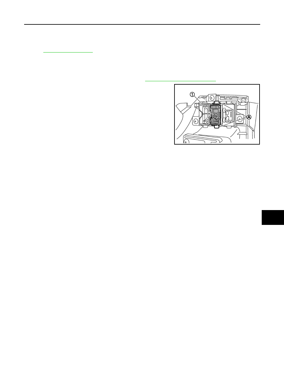
2.
Remove the trunk lid opener switch (1) from instrument driver
lower panel, and then remove pawl (A). Press trunk lid opener
switch (1) front side to disengage from instrument driver lower
panel.
INSTALLATION
Install in the reverse order of removal.
JMKIA0165ZZ