Infiniti G37 Coupe. Manual - part 385


  Index      Infiniti     Infiniti G37 Coupe - service repair manual 2008 year


Search            


Content   ..  383  384  385  386   ..


Infiniti G37 Coupe. Manual - part 385


KEY SLOT ILLUMINATION

DLK-101

< COMPONENT DIAGNOSIS >

[INTELLIGENT KEY SYSTEM]

C

D

E

F

G

H

I

J

L

M

A

B

DLK

N

O

P

KEY SLOT ILLUMINATION

Description

INFOID:0000000001683137

Blinks when Intelligent Key insertion is required.

Component Function Check

INFOID:0000000001683138

1.

CHECK FUNCTION

With CONSULT-III

Check key slot illumination (“KEY SLOT ILLUMI”) Active Test mode with CONSULT-III.

Is the inspection result normal?

YES

>> Key slot function is OK.

NO

>> Refer to 

DLK-101, "Diagnosis Procedure"

.

Diagnosis Procedure

INFOID:0000000001683139

1.

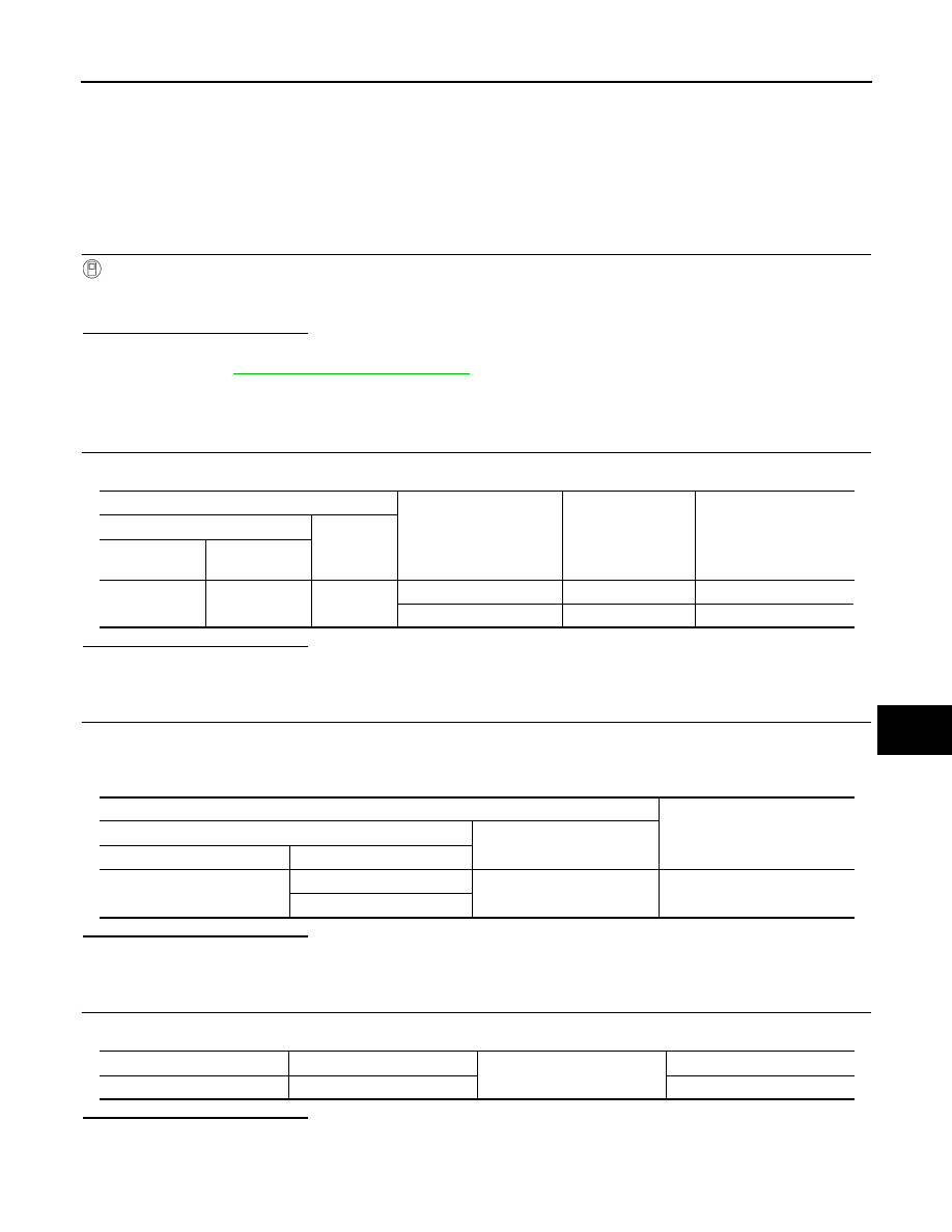
CHECK KEY SLOT ILLUMINATION OUTPUT SIGNAL 

Check voltage between key slot harness connector and ground.

Is the inspection result normal?

YES

>> GO TO 6.

NO

>> GO TO 2.

2.

CHECK KEY SLOT POWER SUPPLY CIRCUIT

1.

Turn ignition switch OFF.

2.

Disconnect key slot connector.

3.

Check voltage between slot harness connector and ground.

Is the inspection result normal?

YES

>> GO TO 3.

NO

>> Repair or replace key slot power supply circuit.

3.

CHECK KEY SLOT GROUND CIRCUIT

Check continuity between key slot harness connector and ground.

Is the inspection result normal?

YES

>> GO TO 4.

NO

>> Repair or replace key slot ground circuit.

Terminals

Condition

Key slot

illumination

Voltage (V)         

 (Approx.)

(+)

(–)

Key slot 

connector

Terminal

M22

6

Ground

Intelligent Key inserted

OFF

Battery voltage

Intelligent Key removed

ON

0

Terminals

Voltage (V)

(Approx.)

(+)

(–)

Key slot connector

Terminal

M22

1

Ground

Battery voltage

5

Key slot connector

Terminal

Ground

Continuity

M22

7

Existed

DLK-102

< COMPONENT DIAGNOSIS >

[INTELLIGENT KEY SYSTEM]

KEY SLOT ILLUMINATION

4.

CHECK KEY SLOT CIRCUIT

1.

Disconnect BCM connector.

2.

Check continuity between BCM harness connector and key slot harness connector.

3.

Check continuity between BCM harness connector and ground.

Is the inspection result normal?

YES

>> GO TO 5.

NO

>> Repair or replace harness between BCM and key slot.

5.

CHECK KEY SLOT 

Refer to 

DLK-72, "Component Inspection"

.

Is the inspection result normal?

YES

>> GO TO 6.

NO

>> Replace key slot. Refer to 

DLK-243, "Removal and Installation"

.

6.

CHECK INTERMITTENT INCIDENT 

Refer to 

GI-38, "Intermittent Incident"

.

>> INSPECTION END

BCM connector

Terminal

Key slot 

connector

Terminal

Continuity

M122

92

M22

6

Existed

BCM connector

Terminal

Ground

Continuity 

M122

92

Not existed

COMBINATION METER DISPLAY FUNCTION

DLK-103

< COMPONENT DIAGNOSIS >

[INTELLIGENT KEY SYSTEM]

C

D

E

F

G

H

I

J

L

M

A

B

DLK

N

O

P

COMBINATION METER DISPLAY FUNCTION

Description

INFOID:0000000001683143

Displays each operation method guide and warning for system malfunction.

Component Function Check

INFOID:0000000001683144

1.

CHECK FUNCTION

With CONSULT-III

Check the operation with (“LCD”) in the Active Test with CONSULT-III.

Is the inspection result normal?

YES

>> Meter display is OK.

NO

>> Refer to 

DLK-103, "Diagnosis Procedure"

.

Diagnosis Procedure

INFOID:0000000001683145

1.

CHECK COMBINATION METER

Refer to 

MWI-35, "Diagnosis Description"

.

Is the inspection result normal?

YES

>> GO TO 2.

NO

>> Check combination meter. Refer to 

MWI-4, "Work flow"

.

2.

CHECK INTERMITTENT INCIDENT

Refer to

GI-38, "Intermittent Incident"

.

>> INSPECTION END.

Is each warning displayed on meter display?

DLK-104

< COMPONENT DIAGNOSIS >

[INTELLIGENT KEY SYSTEM]

BUZZER (COMBINATION METER)

BUZZER (COMBINATION METER)

Description

INFOID:0000000001683146

Performs operation method guide and warning with buzzer.

Component Function Check

INFOID:0000000001683147

1.

CHECK FUNCTION

With CONSULT-III

1.

Check the operation with “INSIDE BUZZER” in the Active Test with CONSULT-III.

2.

Touch “TAKE OUT”, “KNOB”or “KEY”on screen.

Is the inspection result normal?

Yes

>> Warning buzzer into combination meter is OK.

No

>> Refer to 

DLK-104, "Diagnosis Procedure"

.

Diagnosis Procedure

INFOID:0000000001683148

1.

CHECK METER BUZZER CIRCUIT

Refer to 

WCS-23, "Component Function Check"

.

Is the inspection result normal?

Yes

>> GO TO 2.

No

>> Repair or replace meter buzzer circuit.

2.

CHECK INTERMITTENT INCIDENT

Refer to 

GI-38, "Intermittent Incident"

.

>> INSPECTION END.


Content   ..  383  384  385  386   ..