Infiniti G37 Coupe. Manual - part 267
BRC-42
< COMPONENT DIAGNOSIS >
[VDC/TCS/ABS]
C1114 ACTUATOR RELAY SYSTEM
C1114 ACTUATOR RELAY SYSTEM
Description
INFOID:0000000001635062
Activates or deactivates each solenoid valve according to the signals transmitted by the ABS actuator and
electric unit (control unit).
DTC Logic
INFOID:0000000001635063
DTC DETECTION LOGIC
DTC CONFIRMATION PROCEDURE
1.
CHECK SELF-DIAGNOSIS RESULTS
Check the self-diagnosis results.
Is above displayed on the self-diagnosis display?
YES
>> Proceed to diagnosis procedure. Refer to
.
NO
>> INSPECTION END
Diagnosis Procedure
INFOID:0000000001635064
1.
CHECK CONNECTOR
1.
Turn ignition switch OFF.
2.
Disconnect ABS actuator and electric unit (control unit) connector.
3.
Check terminal for deformation, disconnection, looseness, and so on. If any malfunction is found, repair or
replace terminal.
4.
Reconnect connectors and then perform the self-diagnosis.
Is any item indicated on the self-diagnosis display?
YES
>> GO TO 2.
NO
>> Poor connection of connector terminal. Repair or replace connector.
2.
CHECK SOLENOID, VDC SWITCH-OVER VALVE AND ACTUATOR RELAY POWER SUPPLY CIRCUIT
1.
Turn ignition switch OFF.
2.
Disconnect ABS actuator and electric unit (control unit) connector.
3.
Check voltage between ABS actuator and electric unit (control unit) harness connector terminal and
ground.
Is the inspection result normal?
YES
>> GO TO 3.
NO
>> Repair or replace malfunctioning components.
3.
CHECK SOLENOID, VDC SWITCH-OVER VALVE AND ACUATOR RELAY GROUND CIRCUIT
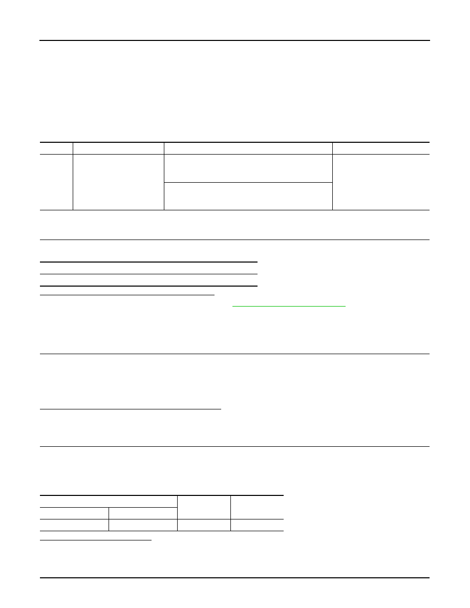
DTC
Display item
Malfunction detected condition
Possible cause
C1114
MAIN RELAY
During the actuator relay operating with OFF, when the
actuator relay turns ON, or when the control line for the
relay is shorted to the ground.
• Harness or connector
• ABS actuator and electric unit
(control unit)
During the actuator relay operating with ON, when the
actuator relay turns ON, or when the control line for the
relay is open.
Self-diagnosis results
MAIN RELAY
ABS actuator and electric unit (control unit)
—
Voltage
Connector
Terminal
E41
3
Ground
Battery voltage