Infiniti G37 Coupe. Manual - part 260
BRC-14
< FUNCTION DIAGNOSIS >
[VDC/TCS/ABS]
TCS
TCS
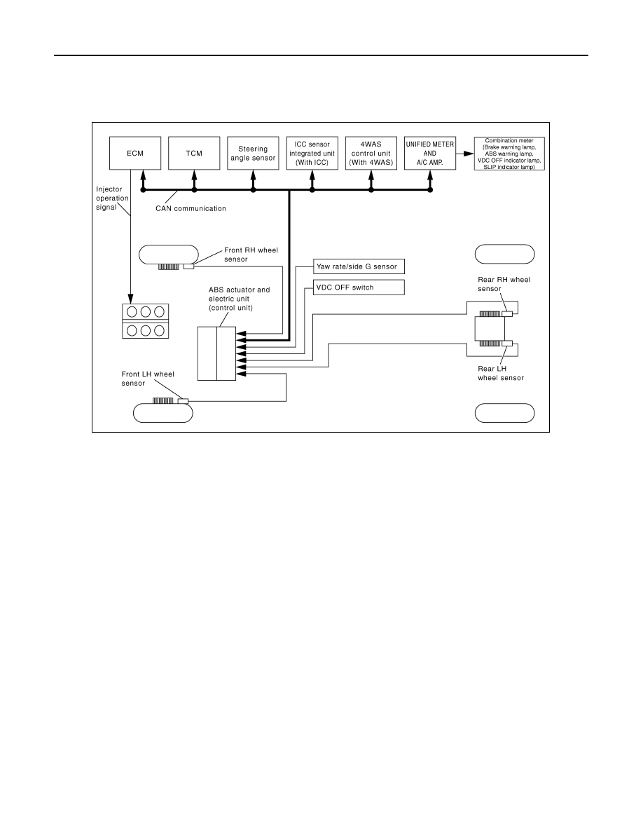
System Diagram
INFOID:0000000001645292
System Description
INFOID:0000000001635028
• Traction Control System is a function that electronically controls engine torque, brake fluid pressure and A/T
gear position to ensure the optimum slippage ratio at drive wheels by computing wheel speed signals from 4
wheel sensors. When ABS actuator and electric unit (control unit) detects a spin at drive wheels (rear
wheels), it compares wheel speed signals from all 4 wheels. At this time, LH and RH rear brake fluid pres-
sure are controlled, while fuel being cut to engine and throttle valve being closed to reduce engine torque by
the control unit. Further more, throttle position is continuously controlled to ensure the optimum engine
torque at all times.
• During TCS operation, it informs driver of system operation by flashing SLIP indicator lamp.
• Electrical system diagnosis by CONSULT-III is available.
JSFIA0124GB