Infiniti G37 Coupe. Manual - part 1363


  Index      Infiniti     Infiniti G37 Coupe - service repair manual 2008 year


Search            


Content   ..  1361  1362  1363  1364   ..


Infiniti G37 Coupe. Manual - part 1363


TRANSMISSION ASSEMBLY

TM-305

< DISASSEMBLY AND ASSEMBLY >

[5AT: RE5R05A]

C

E

F

G

H

I

J

K

L

M

A

B

TM

N

O

P

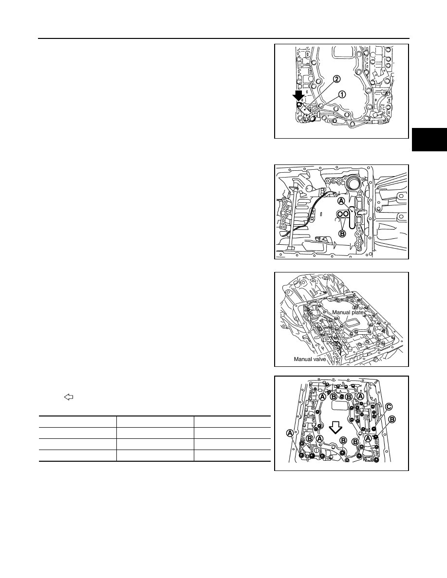
70. Install A/T fluid temperature sensor 2 (1) [with bracket (2)] in

control valve with TCM. Tighten A/T fluid temperature sensor 2
bolt to the specified torque.

CAUTION:

Adjust bolt hole of bracket to bolt hole of control valve.

71. Install control valve with TCM in transmission case.

CAUTION:

• Make sure that turbine revolution sensor securely installs

turbine revolution sensor hole (B). 

• Hang down revolution sensor harness toward outside so

as not to disturb installation of control valve with TCM.

• Adjust A/T assembly harness connector of control valve

with TCM to terminal hole of transmission case.

• Assemble it so that manual valve cutout is engaged with

manual plate projection.

72. Install bolts A, B and C to control valve with TCM.

JPDIA0013ZZ

A

: Brake band

JPDIA0020ZZ

SCIA5035E

: Front

Bolt symbol

Length

mm (in)

Number of bolts

A

42 (1.65)

5

B

55 (2.17)

6

C

40 (1.57)

1

SCIA8077E

TM-306

< DISASSEMBLY AND ASSEMBLY >

[5AT: RE5R05A]

TRANSMISSION ASSEMBLY

73. Tighten bolt 1, 2 and 3 temporarily to prevent dislocation. After

tightening them in order (1 

 2 

 3), tighten other bolts. Tighten

control valve bolts to the TCM with specified torque.

74. Connect A/T fluid temperature sensor 2 connector (A).
75. Engage terminal cord assembly and A/T fluid temperature sen-

sor 2 harness with terminal clips (

).

76. Connect revolution sensor connector (A).

77. Engage revolution sensor harness with terminal clip (

).

78. Pull down A/T assembly harness connector.

CAUTION:

Be careful not to damage connector.

79. Install snap ring to A/T assembly harness connector.

: Front

SCIA8078E

SCIA8124E

JPDIA0011ZZ

SCIA5299E

SCIA5300E

TRANSMISSION ASSEMBLY

TM-307

< DISASSEMBLY AND ASSEMBLY >

[5AT: RE5R05A]

C

E

F

G

H

I

J

K

L

M

A

B

TM

N

O

P

80. Install magnets (1) in oil pan.

81. Install oil pan gasket to transmission case.

CAUTION:

• Do not reuse oil pan gasket.
• Install it in the direction to align hole positions.
• Completely remove all moisture, oil and old gasket, etc. from oil pan gasket mounting surface.

82. Install oil pan (2) and clips (1) to transmission case.

CAUTION:

• Install it so that drain plug (3) comes to the position as

shown in the figure.

• Be careful not to pinch harnesses.
• Completely remove all moisture, oil and old gasket, etc.

from oil pan mounting surface.

83. Tighten oil pan mounting bolts to the specified torque in numeri-

cal order shown in the figure after temporarily tightening them.
Tighten oil pan mounting bolts to the specified torque.

CAUTION:

Do not reuse oil pan mounting bolts.

84. Install drain plug to oil pan. Tighten drain plug to the specified

torque.

CAUTION:

Do not reuse drain plug gasket.

85. Pour ATF into torque converter.

• Approximately 2 liter (2-1/8 US qt, 1-3/4 Imp qt) of ATF is

required for a new torque converter.

• When reusing old torque converter, add the same amount

of ATF as was drained.

JPDIA0009ZZ

: Front

: Oil pan mounting bolt

SCIA8117E

: Front

JPDIA0021ZZ

SAT428DA

TM-308

< DISASSEMBLY AND ASSEMBLY >

[5AT: RE5R05A]

TRANSMISSION ASSEMBLY

86. Install torque converter while aligning notches of torque con-

verter with notches of oil pump.

CAUTION:

Install torque converter while rotating it.

87. Measure distance (A) to make sure that torque converter is in

proper position.

Inspection

INFOID:0000000001672299

INSPECTION AFTER REMOVAL

• Check foreign materials in oil pan to help determine causes of mal-

function. If the ATF is very dark, smells burned, or contains foreign
particles, the frictional material (clutches, band) may need replace-
ment. A tacky film that will not wipe clean indicates varnish build
up. Varnish can cause valves, servo, and clutches to stick and can
inhibit pump pressure.

If frictional material is detected, perform A/T fluid cooler

cleaning. Refer to 

TM-216, "Cleaning"

.

SCIA5010E

B

:  Scale

C

: Straightedge

Distance (A)

: Refer to 

TM-330, "Torque Converter"

.

JPDIA0042ZZ

SCIA5199E


Content   ..  1361  1362  1363  1364   ..