Content .. 1359 1360 1361 1362 ..
Infiniti G37 Coupe. Manual - part 1361
TRANSMISSION ASSEMBLY
TM-297
< DISASSEMBLY AND ASSEMBLY >
[5AT: RE5R05A]
C
E
F
G
H
I
J
K
L
M
A
B
TM
N
O
P
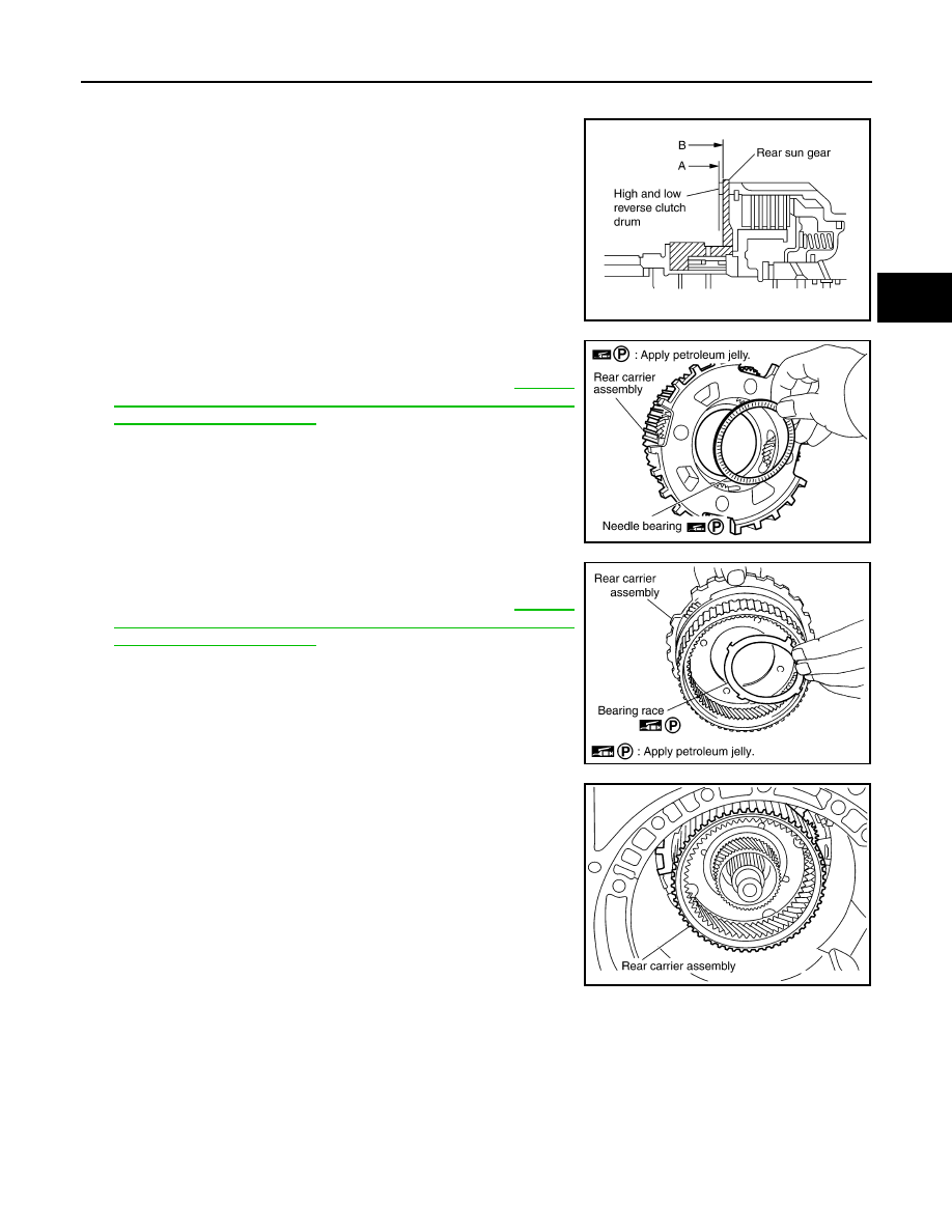
CAUTION:
Make sure that portion “A” of high and low reverse clutch
drum protrudes approximately 2 mm (0.08 in) beyond por-
tion “B” of rear sun gear.
42. Install needle bearing in rear carrier assembly.
CAUTION:
Check the direction of needle bearing. Refer to
"Location of Adjusting Shims, Needle Bearings, Thrust
Washers and Snap Rings"
.
43. Install bearing race in rear carrier assembly.
CAUTION:
Check the direction of needle bearing. Refer to
"Location of Adjusting Shims, Needle Bearings, Thrust
Washers and Snap Rings"
.
44. Install rear carrier assembly in direct clutch drum.
SCIA3130E
SCIA2803E
SCIA5175E
SCIA2462E