Infiniti G37 Coupe. Manual - part 1301


  Index      Infiniti     Infiniti G37 Coupe - service repair manual 2008 year


Search            


Content   ..  1299  1300  1301  1302   ..


Infiniti G37 Coupe. Manual - part 1301


MAIN DRIVE GEAR

TM-57

< DISASSEMBLY AND ASSEMBLY >

[6MT: FS6R31A]

C

E

F

G

H

I

J

K

L

M

A

B

TM

N

O

P

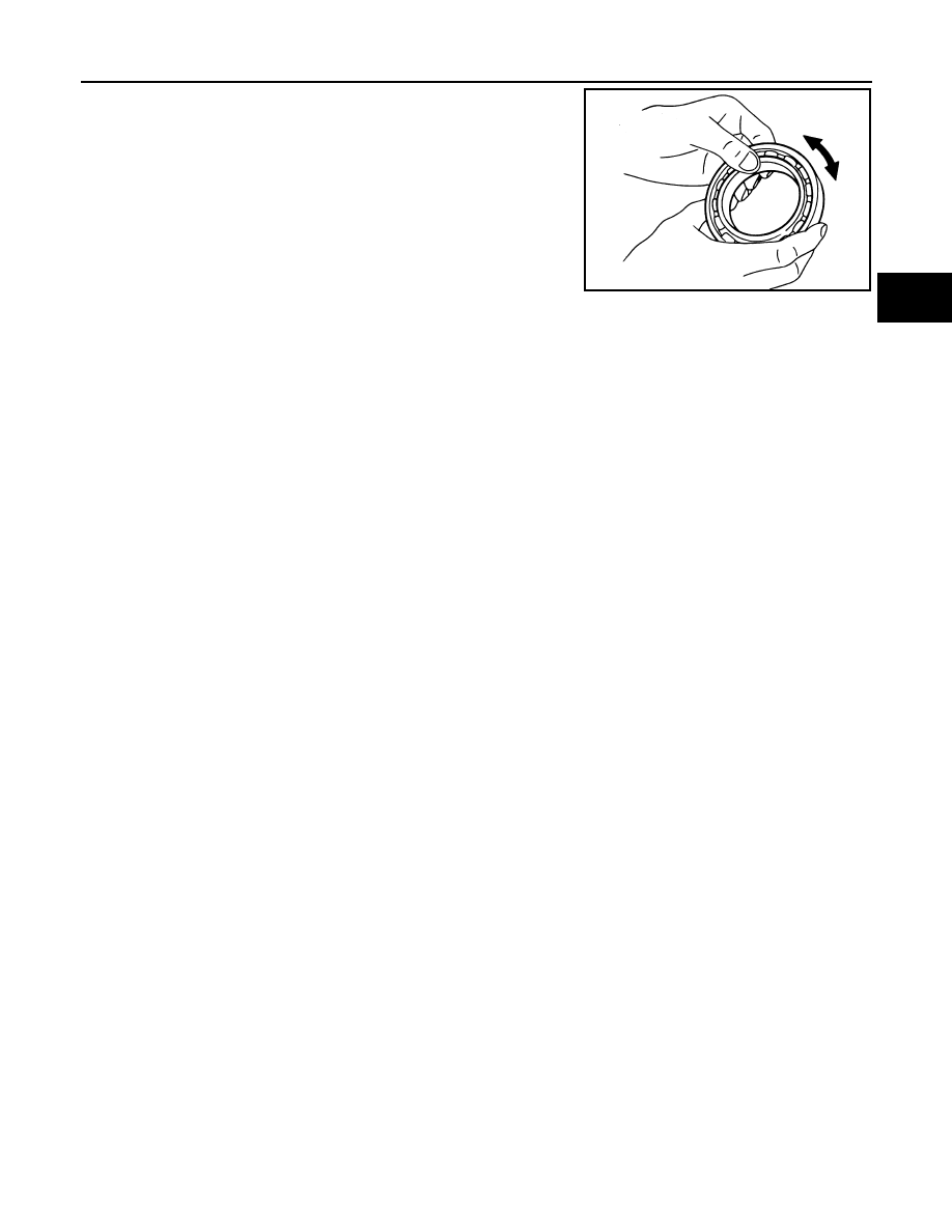
If the bearing does not rotate smoothly or the contact surface on ball
or race is damaged or peeled, replace with new ones.

SMT418A

TM-58

< DISASSEMBLY AND ASSEMBLY >

[6MT: FS6R31A]

MAINSHAFT AND GEAR

MAINSHAFT AND GEAR

Exploded View

INFOID:0000000001732886

Refer to 

TM-29, "Exploded View"

.

Disassembly

INFOID:0000000001732887

1.

Using a press to remove reverse main gear bushing, mainshaft
bearing and 4th main gear.

2.

Remove 3rd-4th main spacer.

3.

Using a press to remove 1st main gear and 3rd main gear.

CAUTION:

Never damage baulk ring.

4.

Remove 1st needle bearing.

5.

Using a press to remove 1st gear bushing, 1st-2nd synchronizer
assembly and 2nd main gear.

CAUTION:

Be aware that when using the press, if mainshaft gear posi-
tioner catches on the V-block, etc., mainshaft could be dam-
aged.

6.

Remove 2nd needle bearing.

7.

After removing snap ring, using a press to remove 6th main gear
and 5th-6th synchronizer assembly.

8.

Remove 6th needle bearing.

Assembly

INFOID:0000000001732888

1.

Install 5th-6th coupling sleeve and 5th-6th shifting inserts in 5th-6th synchronizer hub.

CAUTION:

SCIA1386E

SCIA1458E

SCIA1459E

SCIA1460E

MAINSHAFT AND GEAR

TM-59

< DISASSEMBLY AND ASSEMBLY >

[6MT: FS6R31A]

C

E

F

G

H

I

J

K

L

M

A

B

TM

N

O

P

• Install 5th-6th coupling sleeve with the large chamfer on

the rear side.

• Never reuse 5th-6th coupling sleeve and 5th-6th synchro-

nizer hub.

• Replace 5th-6th coupling sleeve and 5th-6th synchronizer

hub as a set.

2.

Install 5th-6th spread springs in 5th-6th shifting inserts.

CAUTION:

• Never install 5th-6th spread spring hook onto the same

5th-6th shifting insert.

• Be careful with the shape of reverse shifting insert to

avoid misassembly.

3.

Apply recommended grease to 6th needle bearing.

4.

Install 6th needle bearing, 6th main gear and 6th baulk ring on
mainshaft and then using an inserter [SST: ST30911000 (

)] and a press to press fit 5th-6th synchronizer assembly.

CAUTION:

PCIB1362E

SCIA1600E

PCIB0608E

PCIB0219E

TM-60

< DISASSEMBLY AND ASSEMBLY >

[6MT: FS6R31A]

MAINSHAFT AND GEAR

• When press fitting, install with the side having the three

boss edge oil grooves facing the rear side.

NOTE:
5th and 6th baulk rings have three spaces that four gear teeth
are missing as shown in the figure.

5.

Select and install a snap ring so that the end play comes within
the standard value.

CAUTION:

Never reuse snap ring.

6.

Install 1st-2nd coupling sleeve and 1st-2nd shifting inserts into 1st-2nd synchronizer hub.

CAUTION:

• Install 1st-2nd coupling sleeve with the thicker flange

faced the front side.

• Never reuse 1st-2nd coupling sleeve and 1st-2nd syn-

chronizer hub.

• Replace 1st-2nd coupling sleeve and 1st-2nd synchro-

nizer hub as a set.

7.

Install 1st-2nd spread springs in 1st-2nd shifting inserts.

CAUTION:

PCIB1363E

PCIB1330E

End play

Refer to 

TM-75, "End Play"

.

PCIB0609E

PCIB0610E


Content   ..  1299  1300  1301  1302   ..