Infiniti G37 Coupe. Manual - part 1258


  Index      Infiniti     Infiniti G37 Coupe - service repair manual 2008 year


Search            


Content   ..  1256  1257  1258  1259   ..


Infiniti G37 Coupe. Manual - part 1258


U1000, U1002 4WAS COMMUNICATION CIRCUIT

STC-83

< COMPONENT DIAGNOSIS >

[WITH 4WAS]

C

D

E

F

H

I

J

K

L

M

A

B

STC

N

O

P

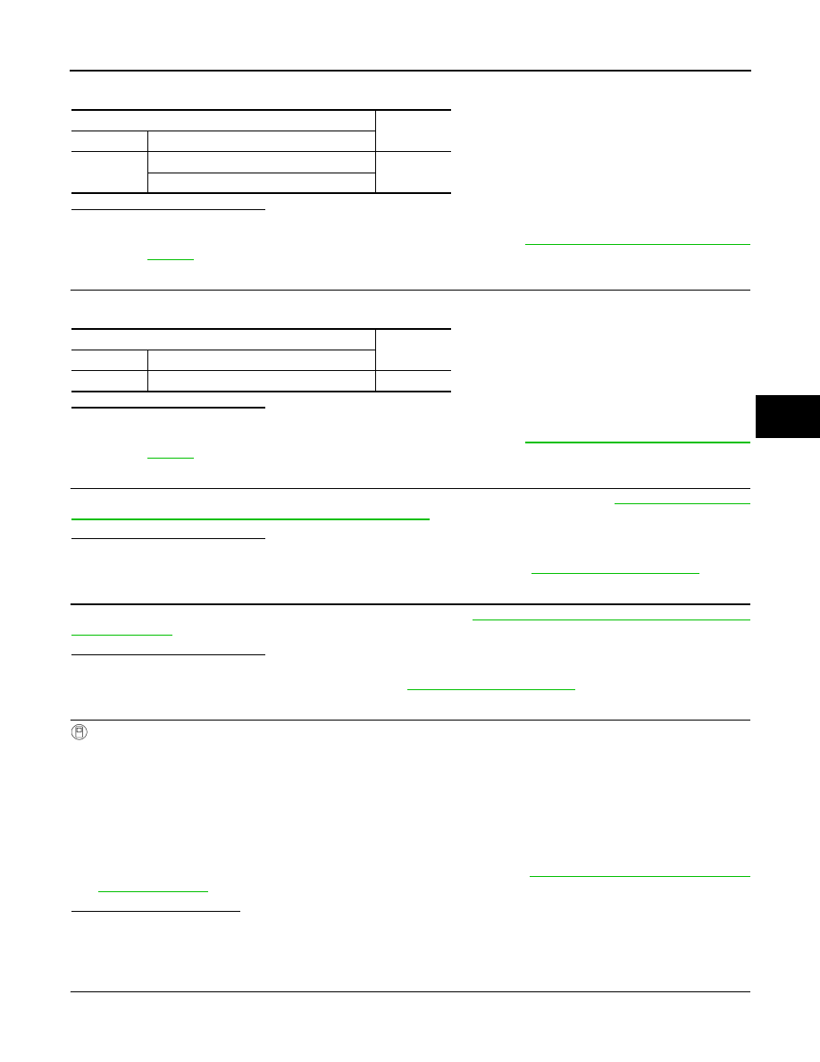
Check the continuity between ABS actuator and electric unit (control unit) harness connector and the ground.

Is the inspection result normal?

YES

>> GO TO 3.

NO

>> Repair or replace the harnesses and connectors. Refer to 

STC-176, "Precautions for Harness

Repair"

.

3.

CHECK COMMUNICATION LINE (3)

Check the continuity between ABS actuator and electric unit (control unit) harness connector.

Is the inspection result normal?

YES

>> GO TO 4.

NO

>> Repair or replace the harnesses and connectors. Refer to 

STC-176, "Precautions for Harness

Repair"

.

4.

CHECK ABS ACTUATOR AND ELECTRIC UNIT (CONTROL UNIT)

Check the continuity between ABS actuator and electric unit (control unit). Refer to 

STC-84, "Component

Inspection [ABS Actuator and Electric Unit (Control Unit)]"

.

Is the inspection result normal?

YES

>> GO TO 5.

NO

>> Replace ABS actuator and electric unit (control unit). Refer to 

BRC-102, "Exploded View"

.

5.

CHECK YAW RATE/SIDE G SENSOR

Check the continuity between yaw rate/side G sensor. Refer to 

STC-84, "Component Inspection (Yaw Rate/

Side G Sensor)"

.

Is the inspection result normal?

YES

>> GO TO 6.

NO

>> Replace yaw rate/side G sensor. Refer to 

BRC-104, "Exploded View"

.

6.

CHECK CAN DIAGNOSIS SUPPORT MONITOR (4WAS FRONT CONTROL UNIT)

With CONSULT-III

1.

Connect ABS actuator and electric unit (control unit) harness connector.

2.

Connect yaw rate/side G sensor harness connector.

3.

Connect 4WAS front control unit harness connector.

4.

Connect 4WAS main control unit harness connector.

5.

Start the engine.

CAUTION:

Stop the vehicle.

6.

Perform CAN diagnosis support monitor of 4WAS front control unit.

7.

Replace 4WAS main control unit error history. Refer to 

STC-39, "CONSULT-III Function

[4WAS(FRONT)]"

.

What is the indicated item?

All items are “OK”>>GO TO 7.
“TRANSMIT DIAG” is other than “OK”>>GO TO 7.
“4WAS(MAIN)” is other than “OK”>>GO TO 8.

7.

CHECK 4WAS FRONT CONTROL UNIT CIRCUIT

1.

Turn the ignition switch OFF.

2.

Disconnect 4WAS front control unit harness connector.

ABS actuator and electric unit (control unit)

Continuity

Connector

Terminal

E41

25 – Ground

Not existed

45 – Ground

ABS actuator and electric unit (control unit)

Continuity

Connector

Terminal

E41

25 – 45

Not existed

STC-84

< COMPONENT DIAGNOSIS >

[WITH 4WAS]

U1000, U1002 4WAS COMMUNICATION CIRCUIT

3.

Disconnect ABS actuator and electric unit (control unit) harness connector.

4.

Check the continuity between 4WAS front control unit harness connector and ABS actuator and electric
unit (control unit) harness connector.

5.

Check that 4WAS front control unit connector No. 14 terminal and No. 25 are connected properly and not
deformed.

Is the inspection result normal?

YES

>> Replace 4WAS front control unit. Refer to 

STC-177, "Exploded View"

.

NO

>> Repair or replace the harnesses and connectors. Refer to 

STC-176, "Precautions for Harness

Repair"

.

8.

CHECK 4WAS MAIN CONTROL UNIT CIRCUIT

1.

Turn the ignition switch OFF.

2.

Disconnect 4WAS main control unit harness connector.

3.

Disconnect ABS actuator and electric unit (control unit) harness connector.

4.

Check the continuity between 4WAS main control unit harness connector and ABS actuator and electric
unit (control unit) harness connector.

5.

Check that 4WAS main control unit connector No. 31 terminal and No. 32 are connected properly and not
deformed.

Is the inspection result normal?

YES

>> Replace 4WAS main control unit. Refer to 

STC-178, "Exploded View"

.

NO

>> Repair or replace the harnesses and connectors. Refer to 

STC-176, "Precautions for Harness

Repair"

.

Component Inspection [ABS Actuator and Electric Unit (Control Unit)]

INFOID:0000000001666381

1.

CHECK ABS ACTUATOR AND ELECTRIC UNIT (CONTROL UNIT)

1.

Turn the ignition switch OFF.

2.

Remove ABS actuator and electric unit (control unit). Refer to 

BRC-102, "Exploded View"

.

3.

Check the resistance between ABS actuator and electric unit (control unit) connector terminals.

Is the inspection result normal?

YES

>> INSPECTION END

NO

>> Replace ABS actuator and electric unit (control unit).

Component Inspection (Yaw Rate/Side G Sensor)

INFOID:0000000001666382

1.

CHECK YAW RATE/SIDE G SENSOR

1.

Turn the ignition switch OFF.

2.

Remove yaw rate/side G sensor. Refer to 

BRC-104, "Exploded View"

.

4WAS front control unit

ABS actuator and electric 

unit (control unit)

Continuity

Connector

Terminal

Connector

Terminal

M42

14

E41

25

Existed

25

45

4WAS main control unit

ABS actuator and electric 

unit (control unit)

Continuity

Connector

Terminal

Connector

Terminal

B54

31

E41

45

Existed

32

25

ABS actuator and electric unit (control unit)

Resistance (Approx.)

Connector

Terminal

E41

25 – 45

120 

U1000, U1002 4WAS COMMUNICATION CIRCUIT

STC-85

< COMPONENT DIAGNOSIS >

[WITH 4WAS]

C

D

E

F

H

I

J

K

L

M

A

B

STC

N

O

P

3.

Check the resistance between yaw rate/side G sensor connector terminals.

Is the inspection result normal?

YES

>> INSPECTION END

NO

>> Replace yaw rate/side G sensor.

Special Repair Requirement

INFOID:0000000001666383

BEFORE REPLACING 4WAS FRONT CONTROL UNIT

• Record the self-diagnosis results (history).

CAUTION:

• Never erase the memory (history) of self-diagnosis results when replacing 4WAS front control unit

after diagnosis.

• Erase the memory of the self-diagnosis results (record) after printing out or recording all the val-

ues of “DATA MONITOR”.

AFTER REPLACING 4WAS FRONT CONTROL UNIT

• Perform 4WAS front actuator adjustment after replacing 4WAS front control unit. Refer to 

STC-28, "4WAS

FRONT ACTUATOR NEUTRAL POSITION ADJUSTMENT : Special Repair Requirement (Pattern 3)"

.

Yaw rate/side G sensor

Resistance (Approx.)

Connector

Terminal

M143

2 – 3

120 

STC-86

< COMPONENT DIAGNOSIS >

[WITH 4WAS]

U1010 4WAS COMMUNICATION CIRCUIT

U1010 4WAS COMMUNICATION CIRCUIT

Description

INFOID:0000000001878363

• 4WAS front control unit and 4WAS main control unit transmit/receive information to/from each other for opti-

mum control of the 4WAS system with the specified 4WAS system line (4WAS communication line) between
4WAS front control unit and 4WAS main control unit.

• Be careful to repair wirings because 4WAS system specified line adopts twisted-pair wires. Refer to 

STC-

176, "Precautions for Harness Repair"

.

DTC Logic

INFOID:0000000001666385

DTC DETECTION LOGIC

*: Communication line between 4WAS front control unit and 4WAS main control unit

DTC CONFIRMATION PROCEDURE

1.

RECHECK DTC

With CONSULT-III

1.

Turn the ignition switch from OFF to ON.

2.

Perform 4WAS front control unit self-diagnosis.

Is DTC “U1010” detected?

YES

>> Proceed to diagnosis procedure. Refer to 

STC-86, "Diagnosis Procedure"

.

NO

>> INSPECTION END

Diagnosis Procedure

INFOID:0000000001666386

1.

4WAS FRONT CONTROL UNIT

Check that there is no malfunction in 4WAS front control unit harness connector or disconnection.

Is the inspection result normal? 

YES

>> Replace 4WAS front control unit. Refer to 

STC-177, "Exploded View"

.

NO

>> Repair or replace the harnesses and connectors. Refer to 

STC-176, "Precautions for Harness

Repair"

.

Special Repair Requirement

INFOID:0000000001666387

BEFORE REPLACING 4WAS FRONT CONTROL UNIT

• Record the self-diagnosis results (history).

CAUTION:

• Never erase the memory (history) of self-diagnosis results when replacing 4WAS front control unit

after diagnosis.

• Erase the memory of the self-diagnosis results (record) after printing out or recording all the val-

ues of “DATA MONITOR”.

AFTER REPLACING 4WAS FRONT CONTROL UNIT

• Perform 4WAS front actuator adjustment after replacing 4WAS front control unit. Refer to 

STC-28, "4WAS

FRONT ACTUATOR NEUTRAL POSITION ADJUSTMENT : Special Repair Requirement (Pattern 3)"

.

DTC

Items

(CONSULT-III screen terms)

Diagnostic item is detected when...

Possible cause

U1010

CONTROL UNIT(CAN)

When detecting error during the initial diagnosis of 
4WAS controller of 4WAS front control unit

4WAS communication 
line*/4WAS main control 
unit/4WAS front control 
unit error


Content   ..  1256  1257  1258  1259   ..