Content .. 1255 1256 1257 1258 ..
Infiniti G37 Coupe. Manual - part 1257
C1684, C1685 4WAS MAIN CONTROL UNIT COMMUNICATION
STC-79
< COMPONENT DIAGNOSIS >
[WITH 4WAS]
C
D
E
F
H
I
J
K
L
M
A
B
STC
N
O
P
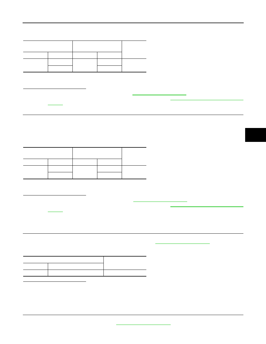
4.
Check the continuity between 4WAS front control unit harness connector and ABS actuator and electric
unit (control unit) harness connector.
5.
Check that 4WAS front control unit connector No. 14 terminal and No. 25 are connected properly and not
deformed.
Is the inspection result normal?
YES
>> Replace 4WAS front control unit. Refer to
.
NO
>> Repair or replace the harnesses and connectors. Refer to
STC-176, "Precautions for Harness
8.
CHECK 4WAS MAIN CONTROL UNIT CIRCUIT
1.
Turn the ignition switch OFF.
2.
Disconnect 4WAS main control unit harness connector.
3.
Disconnect ABS actuator and electric unit (control unit) harness connector.
4.
Check the continuity between 4WAS main control unit harness connector and ABS actuator and electric
unit (control unit) harness connector.
5.
Check that 4WAS main control unit connector No. 31 terminal and No. 32 are connected properly and not
deformed.
Is the inspection result normal?
YES
>> Replace 4WAS main control unit. Refer to
NO
>> Repair or replace the harnesses and connectors. Refer to
STC-176, "Precautions for Harness
Component Inspection [ABS Actuator and Electric Unit (Control Unit)]
INFOID:0000000001666372
1.
CHECK ABS ACTUATOR AND ELECTRIC UNIT (CONTROL UNIT)
1.
Turn the ignition switch OFF.
2.
Remove ABS actuator and electric unit (control unit). Refer to
3.
Check the resistance between ABS actuator and electric unit (control unit) connector terminals.
Is the inspection result normal?
YES
>> INSPECTION END
NO
>> Replace ABS actuator and electric unit (control unit).
Component Inspection (Yaw Rate/Side G Sensor)
INFOID:0000000001666373
1.
CHECK YAW RATE/SIDE G SENSOR
1.
Turn the ignition switch OFF.
2.
Remove yaw rate/side G sensor. Refer to
.
3.
Check the resistance between yaw rate/side G sensor connector terminals.
4WAS front control unit
ABS actuator and electric
unit (control unit)
Continuity
Connector
Terminal
Connector
Terminal
M42
14
E41
25
Existed
25
45
4WAS main control unit
ABS actuator and electric
unit (control unit)
Continuity
Connector
Terminal
Connector
Terminal
B54
31
E41
45
Existed
32
25
ABS actuator and electric unit (control unit)
Resistance (Approx.)
Connector
Terminal
E41
25 – 45
120
Ω