Content .. 1122 1123 1124 1125 ..
Infiniti G37 Coupe. Manual - part 1124
SE-164
< ON-VEHICLE REPAIR >
DRIVER SEAT CONTROL UNIT
DRIVER SEAT CONTROL UNIT
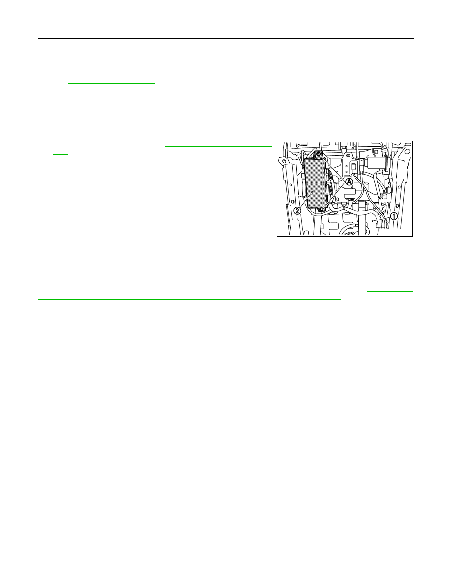
Exploded View
INFOID:0000000001694202
.
Removal and Installation
INFOID:0000000001694203
REMOVAL
CAUTION:
When removing and installing, use shop cloths to protect parts from damage.
1.
Remove driver seat (1). Refer to
SE-152, "Removal and Installa-
2.
Remove mounting bolts (A).
3.
Remove driver seat control unit (2).
INSTALLATION
Install in the reverse order of removal.
CAUTION:
Be sure to clump the harness to the right place.
NOTE:
After installing the driver seat, perform additional service when replacing control unit. Refer to
TIONAL SERVICE WHEN REPLACING CONTROL UNIT : Special Repair Requirement"
JMJIA0230ZZ