Content .. 1071 1072 1073 1074 ..
Infiniti G37 Coupe. Manual - part 1073
SB-14
< ON-VEHICLE REPAIR >
TOP TETHER STRAP CHILD RESTRAINT
TOP TETHER STRAP CHILD RESTRAINT
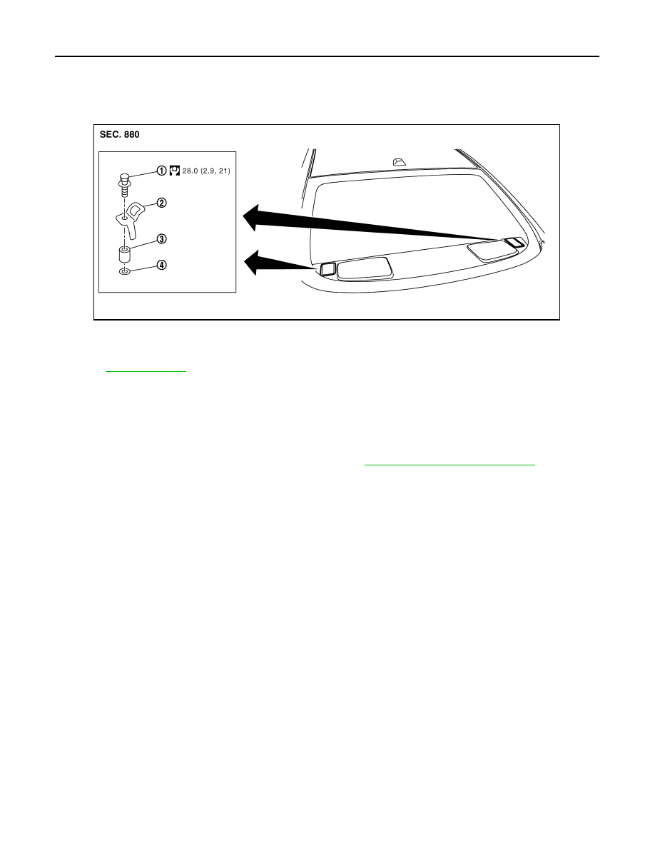
Exploded View
INFOID:0000000001728797
Removal and Installation
INFOID:0000000001728798
REMOVAL
CAUTION:
Replace anchor bolts if they are deformed or worn out.
1.
Remove the top tether strap child restraint cover. Refer to
INT-17, "Removal and Installation"
2.
Remove the top tether strap child restraint.
INSTALLATION
Install in the reverse order of removal.
1.
Anchor bolt
2.
Anchor plate
3.
Spacer
4.
Fiber washer
Refer to
for symbols in the figure.
JMHIA0436GB