Infiniti G37 Coupe. Manual - part 105
AV
AUX IMAGE SIGNAL CIRCUIT
AV-173
< COMPONENT DIAGNOSIS >
[BOSE AUDIO WITHOUT NAVIGATION]
C
D
E
F
G
H
I
J
K
L
M
B
A
O
P
AUX IMAGE SIGNAL CIRCUIT
Description
INFOID:0000000001559038
• Transmits the image signal of AUX device from auxiliary input jacks to AV control unit.
• AV control unit transmits the image signal that is inputted to the display unit.
Diagnosis Procedure
INFOID:0000000001559039
1.
CHECK CONTINUITY AUX IMAGE SIGNAL CIRCUIT (AUX INPUT JACKS AND AV CONTROL UNIT)
1.
Turn ignition switch OFF.
2.
Disconnect auxiliary input jacks connector and AV control unit connector.
3.
Check continuity between auxiliary input jacks harness connector terminal 7 and AV control unit harness
connector terminal 66.
4.
Check continuity between auxiliary input jacks harness connector terminal 7 and ground.
Is the inspection result normal?
YES
>> GO TO 2.
NO
>> Repair harness or connector.
2.
CHECK AUX IMAGE SIGNAL (AUX INPUT JACKS TO AV CONTROL UNIT)
1.
Connect display unit connector and AV control unit connector.
2.
Turn ignition switch ON.
3.
Check signal between auxiliary input jacks harness connector terminal 7 and ground.
Is the inspection result normal?
YES
>> GO TO 3.
NO
>> Check that there is no malfunction in the external device.
3.
CHECK CONTINUITY AUX IMAGE SIGNAL CIRCUIT (AV CONTROL UNIT AND DISPLAY UNIT)
1.
Turn ignition switch OFF.
2.
Disconnect auxiliary input jacks connector and AV control unit connector.
3.
Check continuity between display unit harness connector terminal 15 and AV control unit harness connec-
tor terminal 36.
4.
Check continuity between display unit harness connector terminal 15 and ground.
Is the inspection result normal?
YES
>> GO TO 4.
NO
>> Repair harness or connector.
4.
CHECK AUX IMAGE SIGNAL
7 - 66
: Continuity should exist.
7 - Ground
: Continuity should not exist.
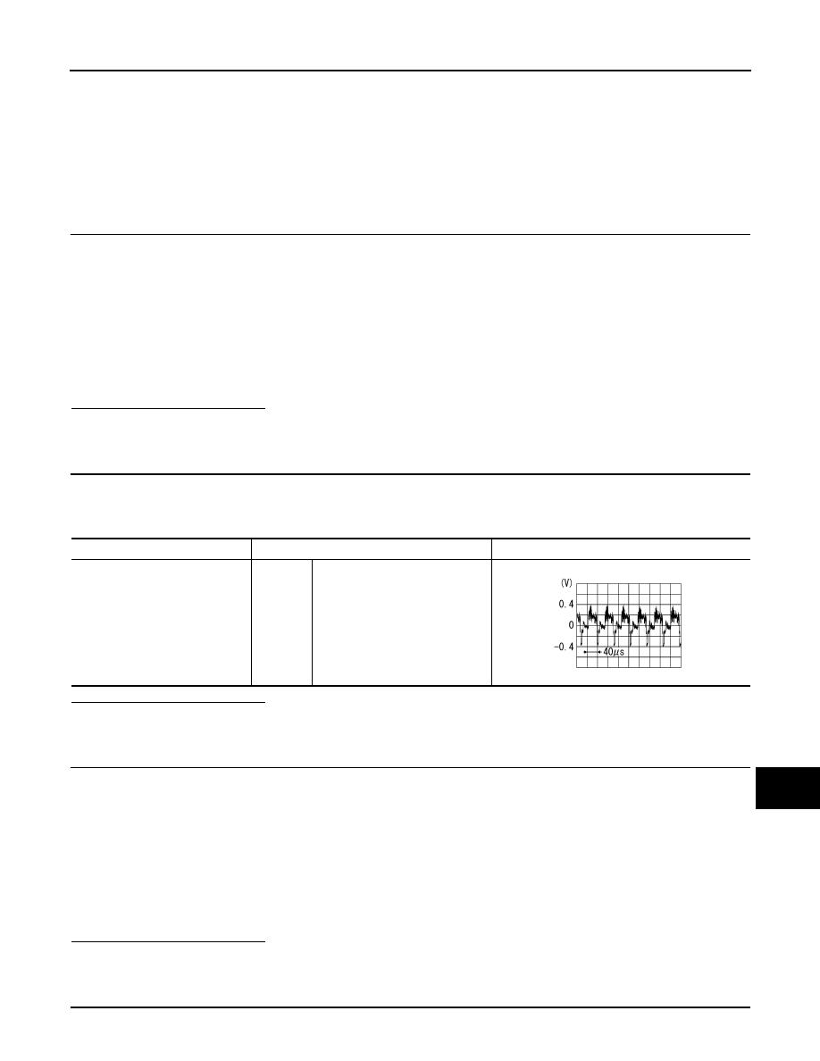
Terminal
Condition
Reference value
7 - Ground
Ignition
switch
ON
At AUX image is displayed.
SKIB2251J
15 - 36
: Continuity should exist.
15 - Ground
: Continuity should not exist.