Infiniti G37 Coupe. Manual - part 1019


  Index      Infiniti     Infiniti G37 Coupe - service repair manual 2008 year


Search            


Content   ..  1017  1018  1019  1020   ..


Infiniti G37 Coupe. Manual - part 1019


POWER WINDOW MOTOR

PWC-17

< COMPONENT DIAGNOSIS >

C

D

E

F

G

H

I

J

L

M

A

B

PWC

N

O

P

Is the inspection result normal?

YES

>> GO TO 4.

NO

>> Repair or replace harness.

4.

CHECK POWER WINDOW MAIN SWITCH OUTPUT SIGNAL

1.

Connect power wimdow main switch connector.

2.

Turn ignition switch ON.

3.

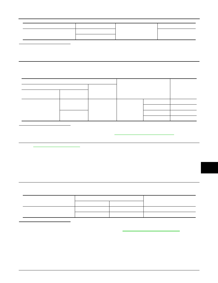
Check voltage between power window main switch connector and ground.

Is the inspection result normal?

YES

>> GO TO 5.

NO

>> Replace power window main switch. Refer to 

PWC-92, "Removal and Installation"

.

5.

CHECK INTERMITTENT INCIDENT

Refer to 

GI-38, "Intermittent Incident"

.

>> INSPECTION END

DRIVER SIDE : Component Inspection

INFOID:0000000001693985

COMPONENT INSPECTION

1.

CHECK DRIVER SIDE POWER WINDOW MOTOR

Check motor operation by connecting the battery voltage directly to driver side power window motor connec-
tor.

Is the inspection result normal?

YES

>> Driver side power window motor is OK.

NO

>> Replace driver side power window motor. Refer to 

GW-19, "Removal and Installation"

.

PASSENGER SIDE

PASSENGER SIDE : Description

INFOID:0000000001693987

Door glass moves UP/DOWN by receiving the signal power window main switch or power window sub-switch .

PASSENGER SIDE : Component Function Check

INFOID:0000000001693988

1.

 CHECK POWER WINDOW MOTOR CIRCUIT

Power window main switch connector

Terminal

Ground

Continuity

D8

8

Not existed

11

Terminal

Power window main switch condition

Voltage (V)

(Approx.)

(+)

(–)

Power window main 

switch connector

Terminal

D8

8

Ground

Driver side

UP

Battery voltage

DOWN

0

11

UP

0

DOWN

Battery voltage

Driver side power window motor con-

nector

Terminal

Motor operation

(+)

(–)

D10

3

6

DOWN

6

3

UP

PWC-18

< COMPONENT DIAGNOSIS >

POWER WINDOW MOTOR

Check passenger side power window motor operation with power window main switch or power window sub
switch.
Is the inspection result normal?

YES

>> Power window motor is OK.

NO

>> Refer to 

PWC-18, "PASSENGER SIDE : Diagnosis Procedure"

.

PASSENGER SIDE : Diagnosis Procedure

INFOID:0000000001693989

1.

CHECK POWER WINDOW SUB-SWITCH OUTPUT SIGNAL

1.

Turn ignition switch OFF.

2.

Disconnect passenger side power window motor connector.

3.

Turn ignition switch ON.

4.

Check voltage between passenger side power window motor harness connector and ground.

Is the measurement value within the specification?

YES

>> GO TO 2.

NO

>> GO TO 3.

2.

CHECK PASSENGER SIDE POWER WINDOW MOTOR 

Check passenger side power window motor. 
Refer to 

PWC-19, "PASSENGER SIDE : Component Inspection"

.

Is the inspection result normal?

YES

>> GO TO 5.

NO

>> Replace passenger side power window motor. Refer to 

GW-19, "Removal and Installation"

.

3.

CHECK HARNESS CONTINUITY

1.

Turn ignition switch OFF.

2.

Disconnect power window sub-switch connector.

3.

Check continuity between power window sub-switch harness connector and passenger side power win-
dow motor harness connector.

4.

Check continuity between power window sub-switch connector and ground.

Is the inspection result normal?

YES

>> GO TO 4.

NO

>> Repair or replace harness.

4.

CHECK POWER WINDOW SUB-SWITCH OUTPUT SIGNAL

1.

Connect power window sub-switch connector.

Terminal

Power window sub- 

switch condition

Voltage (V)

(Approx.)

(+)

(–)

Passenger side power window mo-

tor connector

Terminal 

D40

3

Ground

UP

Battery voltage

DOWN

0

6

UP

0

DOWN

Battery voltage

Power window sub-switch connec-

tor

Terminal

Passenger side power window mo-

tor connector

Terminal

Continuity

D38

9

D40

3

Existed

8

6

Power window sub-switch connector

Terminal

Ground

Continuity

D38

8

Not existed

9

POWER WINDOW MOTOR

PWC-19

< COMPONENT DIAGNOSIS >

C

D

E

F

G

H

I

J

L

M

A

B

PWC

N

O

P

2.

Turn ignition switch ON.

3.

Check voltage between power window sub-switch harness connector and ground.

Is the inspection result normal?

YES

>> GO TO 5.

NO

>> Replace power window sub-switch. Refer to 

PWC-92, "Removal and Installation"

.

5.

CHECK INTERMITTENT INCIDENT

Refer to 

GI-38, "Intermittent Incident"

.

>> INSPECTION END

PASSENGER SIDE : Component Inspection

INFOID:0000000001693990

COMPONENT INSPECTION

1.

CHECK PASSENGER SIDE POWER WINDOW MOTOR

Check motor operation by connecting the battery voltage directly to passenger side power window motor con-
nector.

Is the inspection result normal?

YES

>> Passenger side power window motor is OK.

NO

>> Replace passenger side power window motor. Refer to 

GW-19, "Removal and Installation"

.

Terminal

Power window sub-switch condition

Voltage (V)

(Approx.)

(+)

(–)

Power window sub- 

switch connector

Terminal

D38

9

Ground

Passenger side

UP

Battery voltage

DOWN

0

8

UP

0

DOWN

Battery voltage

Passenger side power window motor 

connector

Terminal

Motor condition

(+)

(–)

D40

3

6

DOWN

6

3

UP

PWC-20

< COMPONENT DIAGNOSIS >

ENCODER

ENCODER

DRIVER SIDE

DRIVER SIDE : Description

INFOID:0000000001694002

Detects condition of the driver side power window motor operation and transmits to power window main switch
as the pulse signal. 

DRIVER SIDE : Component Function Check

INFOID:0000000001694003

1.

CHECK ENCODER OPERATION

Check driver side door glass perform AUTO open/close operation normally when power window main switch.

Is the inspection result normal?

YES

>> Encoder operation is OK.

NO

>> Refer to 

PWC-20, "DRIVER SIDE : Diagnosis Procedure"

.

DRIVER SIDE : Diagnosis Procedure

INFOID:0000000001694004

1.

CHECK ENCODER OPERATION

1.

Turn ignition switch ON.

2.

Check signal between power window main switch harness connector and ground with oscilloscope.

Is the inspection result normal?

YES

>> GO TO 7.

NO

>> GO TO 2.

2.

CHECK ENCORDER SIGNAL CIRCUIT

1.

Turn ignition switch OFF.

2.

Disconnect power window main switch connector and driver side power window motor connector.

3.

Check continuity between power window main switch harness connector and driver side power window
motor harness connector.

4.

Check continuity between power window main switch harness connector and ground.

Terminals

Signal

(Reference value)

(+)

(–)

 Power window main switch 

connector

Terminal 

D8

9

Ground

Refer to following signal

13

JMKIA0220GB

Power window main switch connector

Terminal

Driver side power window motor 

connector

Terminal

Continuity

D8

9

D10

5

Existed

13

2


Content   ..  1017  1018  1019  1020   ..