Infiniti G35 (V35) Sedan. Manual - part 988
PCS-6
< FUNCTION DIAGNOSIS >
[IPDM E/R]
POWER CONTROL SYSTEM
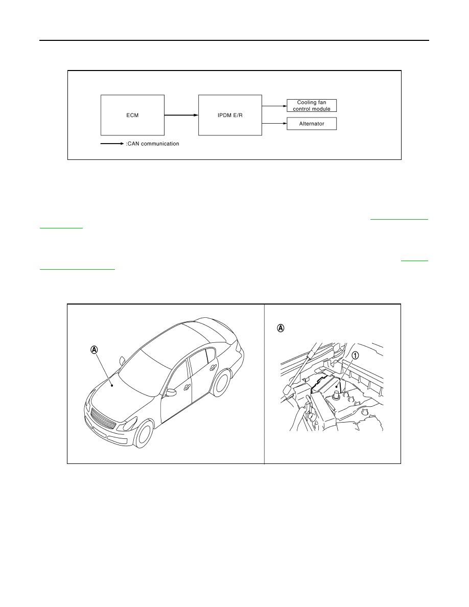
POWER CONTROL SYSTEM
System Diagram
INFOID:0000000000964173
System Description
INFOID:0000000000964174
COOLING FAN CONTROL
IPDM E/R outputs pulse duty signal (PWM signal) to the cooling fan control module according to the status of
the cooling fan speed request signal received from ECM via CAN communication. Refer to
.
ALTERNATOR CONTROL
IPDM E/R outputs power generation command signal (PWM signal) to the alternator according to the status of
the power generation command value signal received from ECM via CAN communication. Refer to
Component Parts Location
INFOID:0000000000964175
JSMIA0004GB
1.
IPDM E/R
A.
Engine room dash panel (RH)
JPMIA0065ZZ