Infiniti G35 (V35) Sedan. Manual - part 986


  Index      Infiniti     Infiniti G35 (V35) Sedan - service repair manual 2007 year


Search            


Content   ..  984  985  986  987   ..


Infiniti G35 (V35) Sedan. Manual - part 986


PB-10

< ON-VEHICLE REPAIR >

PARKING BRAKE SHOE

b.

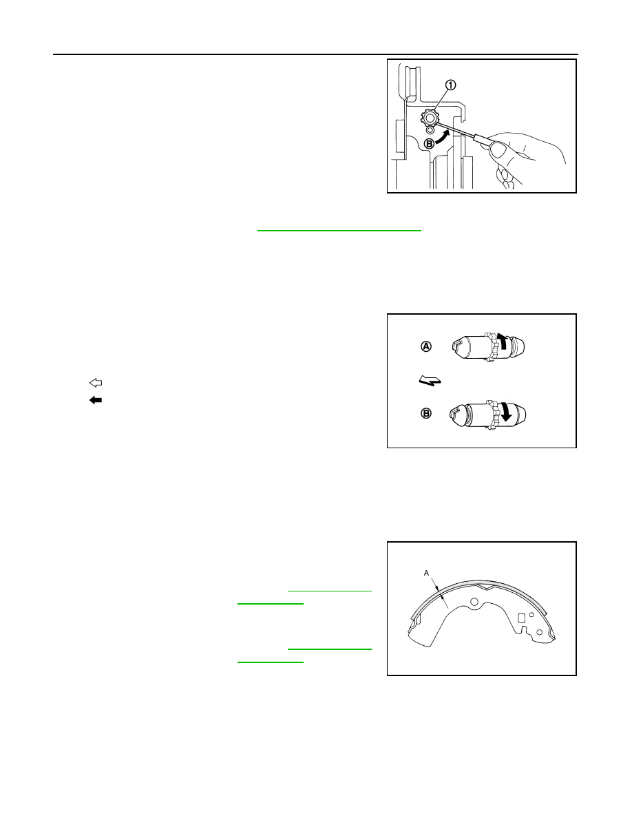
Using suitable tool, rotate adjuster (1) in direction (B) to retract
and loosen brake shoe.

4.

Remove anti-rattle pins, retainers, anti-rattle springs, and return
spring, adjuster spring.

CAUTION:

Never drop the removed parts.

5.

Remove parking brake shoes, adjuster assembly, and toggle
lever.

CAUTION:

• The parking brake shoes for the front wheels are made of

different materials from those for the rear wheels. Never
misidentify them when removing.

• Never drop the removed parts.

6.

For the removal of back plate, refer to 

RAX-7, "Removal and Installation"

.

INSTALLATION

Install in the reverse order of removal.
• Apply PBC (Poly Butyl Cuprysil) grease or silicone-based grease to the back plate and brake shoe.

CAUTION:

The parking brake shoes for the front wheels are made of different materials from those for the rear
wheels. Never misidentify them when removing and replacing.

• Assemble adjusters so that threaded part is expanded when rotat-

ing it in the direction shown by arrow.

• Shorten adjuster by rotating it.
• When disassembling after, apply PBC (Poly Butyl Cuprysil) grease

or silicone-based grease to threads.

• Check brake shoe sliding surface and drum inner surface for

grease. Wipe it off if it adhere on the surfaces.

Inspection and Adjustment

INFOID:0000000000958492

INSPECTION AFTER REMOVAL

Lining Thickness Inspection

• Check thickness (A) of lining.

Drum Inner Diameter Inspection

JPFIB0007ZZ

A: For RH brake

B: For LH brake

 : Vehicle front

 : Adjuster expands

JPFIB0009ZZ

Standard

Standard thickness

: Refer to 

PB-12, "Parking 

Drum Brake"

Limit

Wear limit

: Refer to 

PB-12, "Parking 

Drum Brake"

SBR021A

PARKING BRAKE SHOE

PB-11

< ON-VEHICLE REPAIR >

C

D

E

G

H

I

J

K

L

M

A

B

PB

N

O

P

• Check inner diameter (B) of drum. 

Other Inspections

• Check the lining for excessive wear, damage, and peeling. Replace if necessary.
• Check the brake shoe sliding surface for excessive wear and damage. Replace if necessary.
• Check the anti-rattle pin and retainer for excessive wear, damage and rust. Replace if necessary.
• Check the adjuster spring, return spring and anti-rattle spring for settling, excessive wear, damage, and rust.

Replace if necessary.

• Check the adjuster for smoothness. Replace if necessary.
• Check the toggle lever for excessive wear, damage and rust. Replace if necessary.
• Visually check inside of the drum for excessive wear, cracks, and damage with a pair of vernier calipers.

Replace if necessary.

ADJUSTMENT AFTER INSTALLATION

• Adjust the parking brake pedal stroke or lever stroke. Refer to 

PB-3, "PEDAL TYPE : Inspection and Adjust-

ment"

 (pedal type), 

PB-4, "LEVER TYPE : Inspection and Adjustment"

 (lever type).

• Perform break-in operation as follows after replacing brake shoe and/or disc rotor, or if brakes do not func-

tion well.

1.

Adjust parking brake pedal stroke or lever stroke to the specified amount. Refer to 

PB-3, "PEDAL TYPE :

Inspection and Adjustment"

 (pedal type), 

PB-4, "LEVER TYPE : Inspection and Adjustment"

 (lever type).

2.

Perform parking brake break-in (drag on) operation by driving vehicle under the following conditions:

CAUTION:

To prevent lining from getting too hot, allow a cool off period of approximately 5 minutes after
every break-in operation.

3.

After the break-in procedure, check parking brake pedal stroke or lever stroke of parking brake. If it is out
of the specification, adjust again. Refer to 

PB-3, "PEDAL TYPE : Inspection and Adjustment"

 (pedal type),

PB-4, "LEVER TYPE : Inspection and Adjustment"

 (lever type).

Standard

Standard inner diameter

: Refer to 

PB-12, "Parking 

Drum Brake"

Limit

Wear limit of inner diame-
ter

: Refer to 

PB-12, "Parking 

Drum Brake"

JPFIB0008ZZ

Drive forward

· Vehicle speed

: Approx. 30 km/h (19 MPH) set (constant and forward)

· Parking brake operating force

: Approx. 294 N (30 kg, 66 lb) set constant

· time 

: Approx. 35 sec.

PB-12

< SERVICE DATA AND SPECIFICATIONS (SDS) 

SERVICE DATA AND SPECIFICATIONS (SDS)

SERVICE DATA AND SPECIFICATIONS (SDS)

SERVICE DATA AND SPECIFICATIONS (SDS)

Parking Drum Brake

INFOID:0000000000958493

Unit: mm (in.)

Parking Brake Control

INFOID:0000000000958494

Brake lining

Standard thickness 

3.2 (0.126)

Wear limit

1.5 (0.059)

Drum (disc)

Standard inner diameter

 172 (6.77) dia.

Wear limit of inner diameter

 173 (6.81) dia.

Control type

Pedal type

Lever type

Number of notches [under force of 196 N (20 kg, 44 lb)]

2 – 3 notches

 8 notches

Number of notches when parking brake warning lamp turns ON

1 notch

1 notch

PCS

PCS-1

ELECTRICAL & POWER CONTROL

C

D

E

F

G

H

I

J

K

L

B

SECTION 

PCS

A

O

P

N

CONTENTS

POWER  CONTROL SYSTEM

IPDM E/R

FUNCTION DIAGNOSIS ...............................

3

RELAY CONTROL SYSTEM  ..............................

3

System Diagram ........................................................

3

System Description  ...................................................

3

Component Parts Location ........................................

4

POWER CONTROL SYSTEM  .............................

6

System Diagram ........................................................

6

System Description  ...................................................

6

Component Parts Location ........................................

6

SIGNAL BUFFER SYSTEM  ................................

7

System Diagram ........................................................

7

System Description  ...................................................

7

Component Parts Location ........................................

7

POWER CONSUMPTION CONTROL SYS-
TEM .....................................................................

8

System Diagram ........................................................

8

System Description  ...................................................

8

Component Parts Location ........................................

8

DIAGNOSIS SYSTEM (IPDM E/R) .....................

10

Diagnosis Description  .............................................

10

CONSULT - III Function (IPDM E/R) .......................

12

COMPONENT DIAGNOSIS  .........................

15

U1000 CAN COMM CIRCUIT .............................

15

Description ..............................................................

15

DTC Logic  ...............................................................

15

Diagnosis Procedure ...............................................

15

B2098 IGNITION RELAY ON STUCK  ...............

16

Description ..............................................................

16

DTC Logic  ...............................................................

16

Diagnosis Procedure ...............................................

16

B2099 IGNITION RELAY OFF STUCK ..............

17

Description ...............................................................

17

DTC Logic ................................................................

17

Diagnosis Procedure  ...............................................

17

POWER SUPPLY AND GROUND CIRCUIT  ....

18

Diagnosis Procedure  ...............................................

18

ECU DIAGNOSIS .........................................

19

IPDM E/R (INTELLIGENT POWER DISTRI-
BUTION MODULE ENGINE ROOM)  ................

19

Reference Value ......................................................

19

Wiring Diagram — IPDM E/R — ..............................

26

Fail Safe ..................................................................

29

DTC Index ...............................................................

31

PRECAUTION ..............................................

32

PRECAUTIONS .................................................

32

Precaution for Supplemental Restraint System 
(SRS) "AIR BAG" and "SEAT BELT PRE-TEN-
SIONER" .................................................................

32

Precaution for Procedure without Cowl Top Cover ....

32

ON-VEHICLE REPAIR .................................

33

IPDM E/R (INTELLIGENT POWER DISTRI-
BUTION MODULE ENGINE ROOM)  ................

33

Exploded View .........................................................

33

Removal and Installation  .........................................

33

POWER DISTRIBUTION SYSTEM

BASIC INSPECTION  ...................................

35

DIAGNOSIS AND REPAIR WORKFLOW  ........

35

Work Flow ................................................................

35

FUNCTION DIAGNOSIS ..............................

38

POWER DISTRIBUTION SYSTEM  ...................

38

System Description ..................................................

38

Component Parts Location  ......................................

39


Content   ..  984  985  986  987   ..