Infiniti G35 (V35) Sedan. Manual - part 949


  Index      Infiniti     Infiniti G35 (V35) Sedan - service repair manual 2007 year


Search            


Content   ..  947  948  949  950   ..


Infiniti G35 (V35) Sedan. Manual - part 949


MWI

METER SYSTEM

MWI-23

< FUNCTION DIAGNOSIS >

C

D

E

F

G

H

I

J

K

L

M

B

N

A

O

P

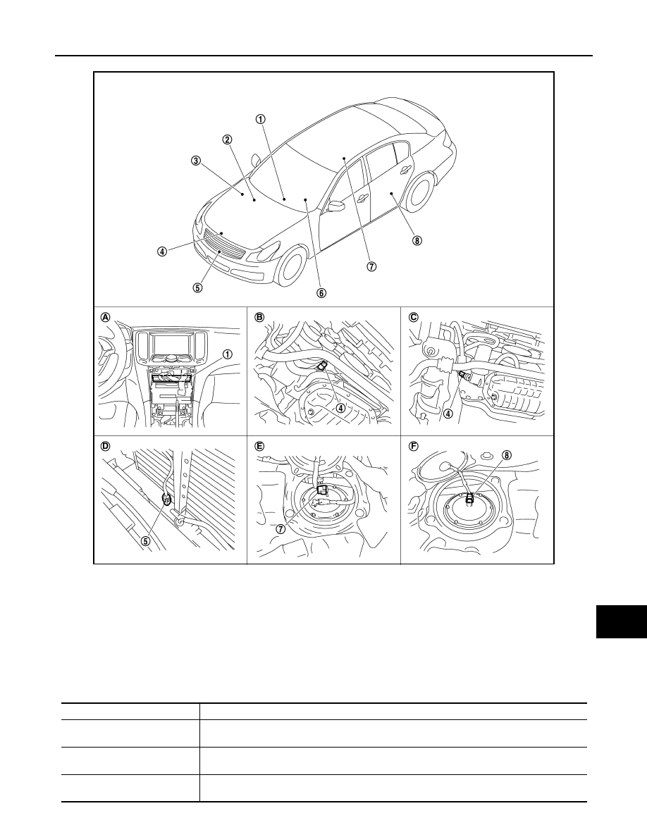
WARNING LAMPS/INDICATOR LAMPS : Component Parts Location

INFOID:0000000000964356

WARNING LAMPS/INDICATOR LAMPS : Component Description

INFOID:0000000000964357

JSNIA0042ZZ

1.

Unified meter and A/C amp.

2.

BCM

3.

IPDM E/R

4.

Oil pressure switch

5.

Ambient sensor

6.

Combination meter

7.

Fuel level sensor unit (main)

8.

Fuel level sensor unit and fuel pump 
(sub)

A.

Behind cluster lid C

B.

2WD [oil pan (upper) RH side]

C.

AWD (oil filter bracket part)

D.

Condenser (front)

E.

Rear seat (lower right)

F.

Rear seat (lower left)

Unit

Description

Combination meter

Turns the oil pressure warning lamp ON/OFF according to the oil pressure switch signal received 
from the unified meter and A/C amp. by means of communication line.

Unified meter and A/C amp.

Transmits the oil pressure switch signal received from the IPDM E/R with BCM to the combination 
meter by means of communication line.

IPDM E/R

IPDM E/R reads the ON/OFF signals from the oil pressure switch and transmits the oil pressure 
switch signal to the unified meter and A/C amp. via BCM with the CAN communication line.

MWI-24

< FUNCTION DIAGNOSIS >

METER SYSTEM

METER ILLUMINATION CONTROL

METER ILLUMINATION CONTROL : System Diagram

INFOID:0000000000964358

METER ILLUMINATION CONTROL : System Description

INFOID:0000000000964359

SYSTEM DESCRIPTION

Meter illumination Control Function

• The combination meter controls the meter illumination by the illumination control switch signal from the

meter control switch and the position light request signal transmitted by BCM with unified meter and A/C
amp.

Daytime Mode

Meter Illumination is adjusted to 5 steps by meter illumination control
switch (1) in daytime mode.

Nighttime Mode

• Combination meter is transferred to nighttime mode with position light request signal from BCM with CAN

communication line.

Oil pressure switch

Refer to 

MWI-58, "Description"

.

BCM

Transmits the oil pressure switch signal received from IPDM E/R via CAN communication to the 
unified meter and A/C amp. via CAN communication line.

Unit

Description

JSNIA0024GB

JSNIA0026GB

MWI

METER SYSTEM

MWI-25

< FUNCTION DIAGNOSIS >

C

D

E

F

G

H

I

J

K

L

M

B

N

A

O

P

• Meter illumination is adjusted to 22 steps by illumination control

switch (1) in nighttime.

METER ILLUMINATION CONTROL : Component Parts Location

INFOID:0000000000964360

JSNIA0026GB

JSNIA0042ZZ

1.

Unified meter and A/C amp.

2.

BCM

3.

IPDM E/R

4.

Oil pressure switch

5.

Ambient sensor

6.

Combination meter

7.

Fuel level sensor unit (main)

8.

Fuel level sensor unit and fuel pump 
(sub)

A.

Behind cluster lid C

B.

2WD [oil pan (upper) RH side]

C.

AWD (oil filter bracket part)

D.

Condenser (front)

E.

Rear seat (lower right)

F.

Rear seat (lower left)

MWI-26

< FUNCTION DIAGNOSIS >

METER SYSTEM

METER ILLUMINATION CONTROL : Component Description

INFOID:0000000000964361

INFORMATION DISPLAY

INFORMATION DISPLAY : System Diagram

INFOID:0000000000964362

INFORMATION DISPLAY : System Description

INFOID:0000000000964363

DISCRIPTION

• The combination meter retrieves the information required for controlling the operations of the information

display from the communication signals from the unified meter and A/C amp., etc.

• The combination meter incorporates a trip computer that displays the warning / information according to the

information received from various units.

PARKING BRAKE RELEASE WARNING

Control outline

The combination meter indicates PARKING BRAKE RELEASE WARNING judged with the vehicle speed sig-
nal received from the unified meter and A/C amp. by means of communication line and the parking brake
switch signal from the parking brake switch.

Warning operation condition

PARKING BRAKE RELEASE is judged if all of the following conditions are fulfilled.

• Vehicle speed is 7 km/h (4.3 MPH) or higher
• Parking brake switch ON

LOW FUEL WARNING

Control outline

• The combination meter indicates LOW FUEL WARNING judged with the fuel level sensor signal received

from the unified meter and A/C amp.

Warning operation condition

• Fuel level: Approx. 12   (3 - 1/8 US gal, 2 - 5/8 Imp gal) or less

LOW WASHER FLUID WARNING

Unit

Description

Combination meter

Controls the meter illumination with the illumination control signal from the meter control switch 
and the position light request signal from unified meter and A/C amp.

Unified meter and A/C amp.

Transmits the position light request signal received from BCM via CAN communication to the com-
bination meter by means of communication.

Meter control switch

Transmits the following signals to the combination meter.

• Illumination control signal (+)

• Illumination control signal (–)

JSNIA0032GB


Content   ..  947  948  949  950   ..