Infiniti G35 (V35) Sedan. Manual - part 947


  Index      Infiniti     Infiniti G35 (V35) Sedan - service repair manual 2007 year


Search            


Content   ..  945  946  947  948   ..


Infiniti G35 (V35) Sedan. Manual - part 947


MWI

METER SYSTEM

MWI-15

< FUNCTION DIAGNOSIS >

C

D

E

F

G

H

I

J

K

L

M

B

N

A

O

P

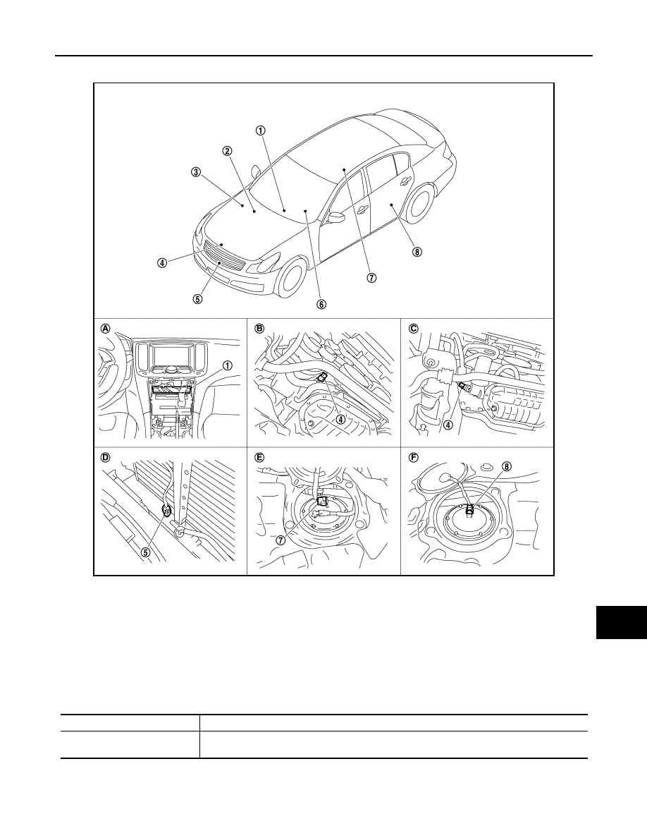
ENGINE COOLANT TEMPERATURE GAUGE : Component Parts Location

INFOID:0000000000964340

ENGINE COOLANT TEMPERATURE GAUGE : Component Description

INFOID:0000000000964341

JSNIA0042ZZ

1.

Unified meter and A/C amp.

2.

BCM

3.

IPDM E/R

4.

Oil pressure switch

5.

Ambient sensor

6.

Combination meter

7.

Fuel level sensor unit (main)

8.

Fuel level sensor unit and fuel pump 
(sub)

A.

Behind cluster lid C

B.

2WD [oil pan (upper) RH side]

C.

AWD (oil filter bracket part)

D.

Condenser (front)

E.

Rear seat (lower right)

F.

Rear seat (lower left)

Unit

Description

Combination meter

Indicates the water temperature gauge according to the engine coolant temperature signal re-
ceived from the unified meter and A/C amp. by means of communication line.

MWI-16

< FUNCTION DIAGNOSIS >

METER SYSTEM

FUEL GAUGE

FUEL GAUGE : System Diagram

INFOID:0000000000964342

FUEL GAUGE : System Description

INFOID:0000000000964343

CONTROL OUTLINE

• The unified meter and A/C amp. reads the fuel level sensor signal from the fuel gauge unit and transmits it to

the combination meter with the communication line.

• The combination meter indicates the fuel level on the fuel gauge according to the received fuel level sensor

signal.

REFUEL CONTROL

The unit judges that the driver is refueling the vehicle and accelerates the fuel gauge needle movement if the
fuel level changes by 15   (4 US gal, 3-3/10 Imp gal) or more.

Unified meter and A/C amp.

Transmits the engine coolant temperature signal received from ECM with CAN communication 
line to the combination meter by means of communication line.

ECM

Transmits the engine coolant temperature signal to the unified meter and A/C amp. with CAN 
communication line.

Unit

Description

JSNIA0023GB

MWI

METER SYSTEM

MWI-17

< FUNCTION DIAGNOSIS >

C

D

E

F

G

H

I

J

K

L

M

B

N

A

O

P

FUEL GAUGE : Component Parts Location

INFOID:0000000000964344

FUEL GAUGE : Component Description

INFOID:0000000000964345

JSNIA0042ZZ

1.

Unified meter and A/C amp.

2.

BCM

3.

IPDM E/R

4.

Oil pressure switch

5.

Ambient sensor

6.

Combination meter

7.

Fuel level sensor unit (main)

8.

Fuel level sensor unit and fuel pump 
(sub)

A.

Behind cluster lid C

B.

2WD [oil pan (upper) RH side]

C.

AWD (oil filter bracket part)

D.

Condenser (front)

E.

Rear seat (lower right)

F.

Rear seat (lower left)

Unit

Description

Combination meter

Indicates the fuel gauge according to the fuel level sensor signal received from the unified meter 
and A/C amp. by means of communication line.

Unified meter and A/C amp.

Transmits the fuel level sensor signal from the fuel level sensor unit to the combination meter by 
means of communication line.

Fuel level sensor unit

Refer to 

MWI-53, "Description"

.

MWI-18

< FUNCTION DIAGNOSIS >

METER SYSTEM

ODO/TRIP METER

ODO/TRIP METER : System Diagram

INFOID:0000000000964346

ODO/TRIP METER : System Description

INFOID:0000000000964347

• The unified meter and A/C amp. transmits the vehicle speed signal from ABS actuator and electric unit (con-

trol unit) to the combination meter.

• The combination meter calculates the vehicle distance according to the vehicle speed signal. The vehicle

distance is displayed.

JSNIA0022GB


Content   ..  945  946  947  948   ..