Infiniti G35 (V35) Sedan. Manual - part 837


  Index      Infiniti     Infiniti G35 (V35) Sedan - service repair manual 2007 year


Search            


Content   ..  835  836  837  838   ..


Infiniti G35 (V35) Sedan. Manual - part 837


LAN

TROUBLE DIAGNOSIS

LAN-17

< FUNCTION DIAGNOSIS >

[CAN FUNDAMENTAL]

C

D

E

F

G

H

I

J

K

L

B

A

O

P

N

Example: Vehicle Display 

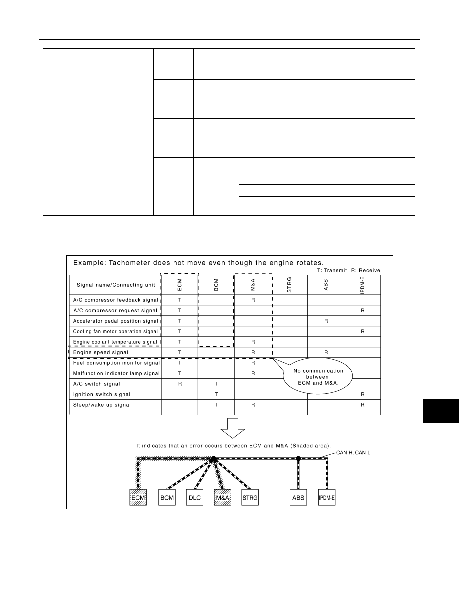
How to Use CAN Communication Signal Chart

INFOID:0000000000963933

The CAN communication signal chart lists the signals needed for trouble diagnosis. It is useful for detecting
the root cause by finding a signal related to the symptom, and by checking transmission and reception unit.

Item

Result indi-

cated

Error counter

Description

CAN_COMM

(Initial diagnosis)

OK

0

Normal at present

NG

1 – 50

Control unit error
(The number indicates how many times diagnosis has been 
run.)

CAN_CIRC_1

(Transmission diagnosis)

OK

0

Normal at present

UNKWN

1 – 50

Unable to transmit for 2 seconds or more at present.
(The number indicates how many times diagnosis has been 
run.)

CAN_CIRC_2 – 9

(Reception diagnosis of each unit)

OK

0

Normal at present

UNKWN

1 – 50

Unable to transmit for 2 seconds or more at present.
(The number indicates how many times diagnosis has been 
run.)

Diagnosis not performed.

No control unit for receiving signals. (No applicable optional 
parts)

SKIB8715E

LAN-18

< BASIC INSPECTION >

[CAN FUNDAMENTAL]

DIAGNOSIS AND REPAIR WORKFLOW

BASIC INSPECTION

DIAGNOSIS AND REPAIR WORKFLOW

Trouble Diagnosis Flow Chart

INFOID:0000000000963934

Trouble Diagnosis Procedure

INFOID:0000000000963935

INTERVIEW WITH CUSTOMER

Interview with the customer is important to detect the root cause of CAN communication system errors and to
understand vehicle condition and symptoms for proper trouble diagnosis.

Points in interview

• What: Parts name, system name
• When: Date, Frequency
• Where: Road condition, Place
• In what condition: Driving condition/environment
• Result: Symptom
NOTE:
• Check normal units as well as error symptoms.
- Example: Circuit between ECM and the combination meter is judged normal if the customer indicates

tachometer functions normally.

• When a CAN communication system error is present, multiple control units may malfunction or go into fail-

safe mode.

JSMIA0016GB

LAN

DIAGNOSIS AND REPAIR WORKFLOW

LAN-19

< BASIC INSPECTION >

[CAN FUNDAMENTAL]

C

D

E

F

G

H

I

J

K

L

B

A

O

P

N

• Indication of the combination meter is important to detect the root cause because it is the most obvious from

the customer, and it performs CAN communication with many units.

INSPECTION OF VEHICLE CONDITION

Check whether the symptom is reproduced or not.
NOTE:
Never turn the ignition switch OFF or disconnect the battery cable while the reproducing the error. The error
may temporarily correct itself, making it difficult to determine the root cause.

CHECK OF CAN SYSTEM TYPE (HOW TO USE CAN SYSTEM TYPE SPECIFICATION CHART)

Determine CAN system type based on vehicle equipment.
NOTE:
• This chart is used if CONSULT-III does not automatically recognize CAN system type.
• There are two styles for CAN system type specification charts. Depending on the number of available sys-

tem types, either style A or style B may be used.

CAN System Type Specification Chart (Style A)

NOTE:

SKIB8717E

LAN-20

< BASIC INSPECTION >

[CAN FUNDAMENTAL]

DIAGNOSIS AND REPAIR WORKFLOW

CAN system type is easily checked with the vehicle equipment identification information shown in the chart.

CAN System Type Specification Chart (Style B)

NOTE:

JSMIA0017GB


Content   ..  835  836  837  838   ..