Infiniti G35 (V35) Sedan. Manual - part 769
HAC-48
< FUNCTION DIAGNOSIS >
[AUTOMATIC AIR CONDITIONER]
DIAGNOSIS SYSTEM (AUTO AMP.)
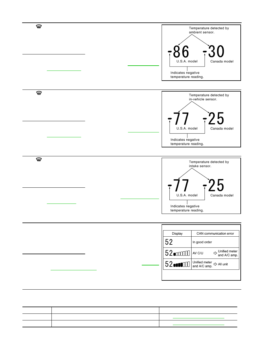
Press
(DEF) switch one time. Temperature detected by ambient
sensor is indicated on the display.
NOTE:
If the temperature indicated on the display greatly differs from the
actual temperature, check sensor circuit first, and then check sensor.
Is the inspection result normal?
YES
>> GO TO 8.
NO
>> Go to Ambient Sensor Circuit. Refer to
.
8.
CHECK IN-VEHICLE SENSOR
Press
(DEF) switch for the second time. Temperature detected
by in-vehicle sensor is indicated on the display.
NOTE:
If the temperature indicated on the display greatly differs from the
actual temperature, check sensor circuit first, and then check sensor.
Is the inspection result normal?
YES
>> GO TO 9.
NO
>> Go to In-vehicle Sensor Circuit. Refer to
.
9.
CHECK INTAKE SENSOR
Press
(DEF) switch for the third time. Temperature detected by
intake sensor is indicated on the display.
NOTE:
If the temperature indicated on the display greatly differs from the
actual temperature, check sensor circuit first, and then check sensor.
Is the inspection result normal?
YES
>> GO TO 10.
NO
>> Go to Intake Sensor Circuit. Refer to
10.
CHECK CAN COMMUNICATION ERROR
1.
Press intake switch.
2.
CAN communication error between each unit that uses the uni-
fied meter and A/C amp. can be detected as self-diagnosis
results. (If plural errors occur, the display of each error will blink
twice for 0.5 second intervals.)
Is the inspection result normal?
YES
>> INSPECTION END
NO
>>
Go to CAN communication. Refer to
.
• Unified meter and A/C amp. - AV control unit
11.
CHECK MALFUNCTIONING SENSOR AND DOOR MOTOR
Refer to the following chart for malfunctioning code No.
(If two or more sensors and door motor malfunction, corresponding code Nos. indicates 1 second each.)
PJIA0151E
PJIA0152E
PJIA0153E
JSIIA0138GB
Code No.
Malfunctioning sensor and door motor (Including circuits)
Reference page
21 /
−
21
Ambient sensor
22 /
−
22
In-vehicle sensor