Infiniti G35 (V35) Sedan. Manual - part 741
GW-22
< ON-VEHICLE REPAIR >
REAR REGULATOR
REAR REGULATOR
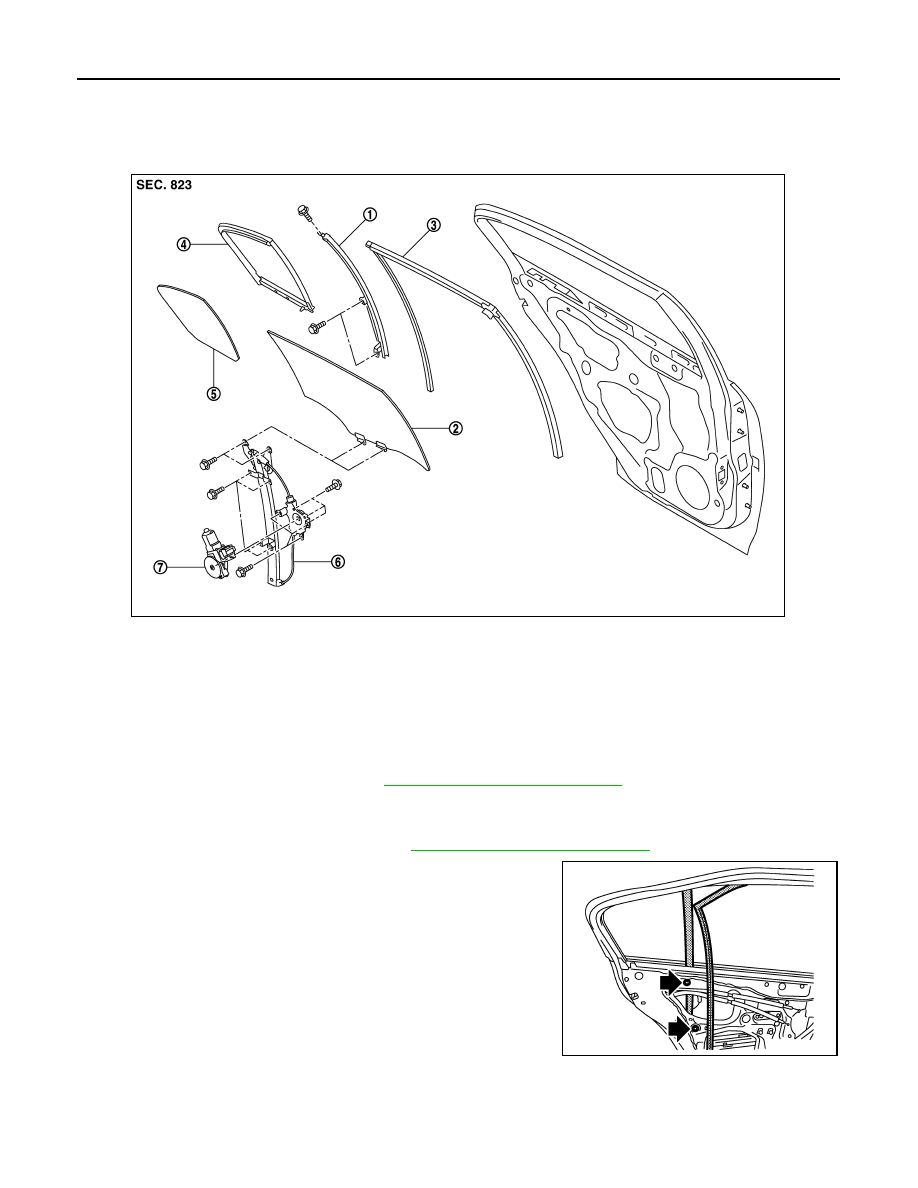
Exploded View
INFOID:0000000000961530
Removal and Installation
INFOID:0000000000961531
REMOVAL
1.
Remove the rear door finisher. Refer to
INT-10, "Removal and Installation"
.
2.
Disconnect the rear door speaker connector.
3.
Remove the sealing screen.
4.
Remove the rear door cover inner. Refer to
INT-10, "Removal and Installation"
5.
Remove the door glass run on the partition sash side.
6.
Remove the partition sash fixing screw and bolts and remove
the partition sash.
1.
Partition sash
2.
Door glass
3.
Door glass run
4.
Partition glass run
5.
Partition glass
6.
Regulator assembly
7.
Power window motor
JMKIA0004ZZ
JMKIA0008ZZ